|
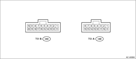
Terminal No. |
Remarks |
Measuring condition |
Standard | |
|
B9 |
Mode door actuator power supply |
Switch the outlet opening to VENT → DEF. |
*2 | |
|
B8 |
Switch the outlet opening to DEF → VENT. | |||
|
B7 |
Air mix door actuator power supply |
Switching the air mix door from COOL → HOT |
*1 | |
|
B6 |
Switching the air mix door from HOT → COOL | |||
|
B5 |
Ignition power supply |
Ignition switch: ON |
Battery voltage | |
|
B4 |
Battery power supply |
Ignition switch: OFF, ACC, ON |
Battery voltage | |
|
B3 |
Sunload sensor |
Ignition switch: ON, With Normal Sunload (No sunload: 5 V) |
3 V | |
|
B2 |
Evaporator sensor |
Ignition switch: ON |
5 V or less | |
|
B1 |
Air mix door actuator PBR signal |
Air mix door: COOL position |
0.5 V | |
|
Air mix door: HOT position |
4.5 V | |||
|
B20 |
Intake door actuator signal |
Inlet opening: FRESH (Other positions: 12 V) |
0 V | |
|
B19 |
Inlet opening: MIX (Other positions: 12 V) |
0 V | ||
|
B18 |
Inlet opening: RECIRC (Other positions: 12 V) |
0 V | ||
|
B17 |
A/C ON signal |
A/C: ON (A/C OFF: 0 V) |
8 — 10 V | |
|
B16 |
Blower motor control |
*3 |
*3 | |
|
B15 |
Blower fan ON signal |
When blower fan is rotating (Not rotating: 12 V) |
0 V | |
|
B13 |
Engine coolant temperature |
When the engine coolant temperature is 49°C (120°F) |
8.9 V | |
|
B12 |
In-vehicle sensor |
— |
— | |
|
B11 |
Ground |
Continuity to chassis ground |
0 Ω | |
|
A7 |
Air mix door actuator PBR specified voltage |
Ignition switch: ON |
5 V | |
|
A5 |
Mode door actuator position detection signal |
Outlet opening |
BI-LEVEL, DEF |
5 V |
|
VENT, HEAT, DEF/HEAT |
0 V | |||
|
A4 |
Mode door actuator position detection signal |
Outlet opening |
HEAT, DEF/HEAT, DEF |
5 V |
|
VENT, BI-LEVEL |
0 V | |||
|
A1 |
Illumination power supply |
Ignition switch: ON, Light switch: ON |
Battery voltage | |
|
Ignition switch: ON, Light switch: OFF |
0 V | |||
|
A16 |
Sensor ground |
Continuity to chassis ground |
0 Ω | |
|
A14 |
Combination meter (Ambient temperature signal) |
*3 |
*3 | |
|
A13 |
Mode door actuator position detection signal |
Outlet opening |
VENT, BI-LEVEL, HEAT |
5 V |
|
DEF/HEAT, DEF |
0 V | |||
|
A12 |
Mode door actuator position detection signal |
Outlet opening |
VENT, DEF/HEAT |
5 V |
|
BI-LEVEL, HEAT, DEF |
0 V | |||
|
A10 |
A/C cut signal |
A/C: ON |
Battery voltage | |
|
When pressure SW is operating |
0 V | |||
|
A9 |
Illumination ground |
Continuity to chassis ground |
0 Ω | |
*1: Shows the battery voltage while the motor is running. When stopped, it will output 0 V, or the pulse signals of the battery voltage.
*2: Shows the battery voltage while the motor is running. When stopped, it shows 0 V.
*3: Unable to measure the voltage because it is a pulse signal.