1.CHECK POWER SUPPLY FOR AIR MIX DOOR ACTUATOR POSITION SWITCH.
1) Turn the ignition switch to OFF.
2) Disconnect the air mix door actuator connector.
3) Turn the ignition switch and AUTO switch to ON.
4) Measure the voltage between auto A/C control module connector terminals.
Connector & terminal
(i48) No. 7 (+) — (i48) No. 16 (−):
|
Is the voltage approx. 5 V?
|
|
Replace the auto A/C control module.
|
2.CHECK POWER SUPPLY FOR AIR MIX DOOR ACTUATOR.
Measure the voltage between auto A/C control module connector and chassis ground after turning the temperature control dial to maximum COOL position.
Connector & terminal
(i49) No. 6 (+) — Chassis ground (−):
|
Is the voltage 7 V (at normal temperature)?
|
|
Replace the auto A/C control module.
|
3.CHECK POWER SUPPLY FOR AIR MIX DOOR ACTUATOR.
Measure the voltage between auto A/C control module connector and chassis ground after turning the temperature control dial to maximum HOT position.
Connector & terminal
(i49) No. 7 (+) — Chassis ground (−):
|
Is the voltage 7 V (at normal temperature)?
|
|
Replace the auto A/C control module.
|
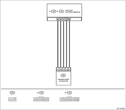
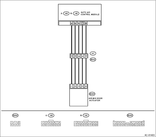
4.CHECK HARNESS BETWEEN AUTO A/C CONTROL MODULE AND AIR MIX DOOR ACTUATOR.
1) Turn the A/C and ignition switch to OFF.
2) Disconnect the auto A/C control module connector.
3) Measure the resistance between auto A/C control module and air mix door actuator connector.
Connector & terminal
LHD model:
(i65) No. 1 — (i49) No. 1:
(i65) No. 2 — (i49) No. 7:
(i65) No. 3 — (i48) No. 16:
(i65) No. 4 — (i48) No. 7:
(i65) No. 6 — (i49) No. 6:
RHD model:
(B293) No. 1 — (i49) No. 1:
(B293) No. 2 — (i49) No. 7:
(B293) No. 3 — (i48) No. 16:
(B293) No. 4 — (i48) No. 7:
(B293) No. 6 — (i49) No. 6:
|
Is the resistance less than 1 Ω?
|
|
Repair the harness between auto A/C control module and air mix door actuator.
|
5.CHECK AIR MIX DOOR ACTUATOR POSITION SWITCH SIGNAL.
1) Connect the connector of auto A/C control module and air mix door actuator.
2) Turn the ignition switch and AUTO switch to ON.
3) Check the voltage between auto A/C control module connector terminals while changing the setting temperature between maximum COOL and maximum HOT.
Connector & terminal
(i49) No. 1 (+) — (i48) No. 16 (−):
|
Does the voltage change between 0.5 V (Max. HOT) and 4.5 V (Max. COOL)?
|
|
Replace the air mix door actuator.
|
6.CHECK POOR CONTACT.
Check poor contact of auto A/C control module and connector.
|
Is there poor contact of the connector?
|
|
Replace the auto A/C control module.
|