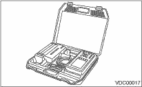
1. Prepare the Subaru Select Monitor kit.
2. Connect the diagnosis cable to the Subaru Select Monitor.
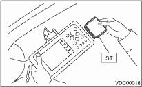
3. Insert the cartridge to the Subaru Select Monitor. 
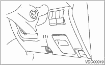
4. Connect the Subaru Select Monitor to the data link connector.
(1) Data link connector is located in the lower portion of the instrument panel (on the driver’s side).
|
(1) |
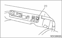
Data link connector |
(2) Connect the diagnosis cable to the data link connector.
5. Turn the ignition switch to ON (engine is OFF), and the Subaru Select Monitor switch to ON.
|
(1) |
Power switch |
6. On the «Main Menu» display screen, select the {Each System Check} and press the [YES] key.
7. On the «System Selection Menu» display screen, select the {Brake Control} and press the [YES] key.
8. Press the [YES] key after the VDC type is displayed.
9. On the «Brake Control Diagnosis» screen, select the {Diagnostic Code(s) Display}, and then press the [YES] key.
NOTE:
• For details concerning operation procedure, refer to the “SUBARU SELECT MONITOR OPERATION MANUAL”.
• For details concerning DTC, refer to “List of Diagnostic Trouble Code (DTC)”.
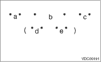
10. A maximum of three DTCs are displayed in the order of occurrence.
|
*a*: |
DTC (2 digits) |
|
*b*: |
Trouble contents |
|
*c*: |
Shows the order of failure occurrence. (Current, previous, second previous, third previous) |
|
*d*: |
Detail DTC (4 digits) |
|
*e*: |
IG/ON count after failure occurred (Maximum of 254) |
|
Display |
Contents of Display |
|
Old |
The latest DTC of the failures in the past is displayed on the Subaru Select Monitor display. |
|
Second previous |
The second latest DTC of the failures in the past is displayed on the Subaru Select Monitor display. |
|
Third previous |
The third latest DTC of the failures in the past is displayed on the Subaru Select Monitor display. |
* If the failure is occurring, “Current” is displayed on the screen.
1. On the «Main Menu» display screen, select the {Each System Check} and press the [YES] key.
2. On the «System Selection Menu» display screen, select the {Brake Control} and press the [YES] key.
3. Press the [YES] key after the VDC type is displayed.
4. On the «Brake Control Diagnosis» display screen, select the {Current Data Display/Save}, and then press the [YES] key.
5. On the «Data Display Menu» screen, select the {Data Display} and press the [YES] key.
6. Using the scroll key, scroll the display screen up or down until the desired data is shown on the screen.
• A list of the support data is shown in the following table.
|
Display |
Contents to be monitored |
Unit of measure |
|
FR Wheel Speed |
Wheel speed detected by front ABS wheel speed sensor RH is displayed. |
km/h |
|
FL Wheel Speed |
Wheel speed detected by front ABS wheel speed sensor LH is displayed. |
km/h |
|
RR Wheel Speed |
Wheel speed detected by rear ABS wheel speed sensor RH is displayed. |
km/h |
|
RL Wheel Speed |
Wheel speed detected by rear ABS wheel speed sensor LH is displayed. |
km/h |
|
Steering Angle Sensor |
Steering wheel angle detected by steering angle sensor is displayed. |
deg |
|
Yaw Rate Sensor |
Vehicle angular speed detected by yaw rate sensor is displayed. |
deg (deg/s) |
|
Pressure Sensor (P) |
Brake fluid pressure detected by the primary pressure sensor is displayed. |
bar |
|
Pressure Sensor (S) |
Brake fluid pressure detected by the secondary pressure sensor is displayed. |
bar |
|
Lateral G Sensor |
Vehicle lateral direction acceleration detected by lateral G sensor is displayed. |
m/s (m/s2) |
|
IG Power Supply Voltage |
Voltage supplied to the VDCCM is displayed. |
V |
|
Valve Relay Signal |
The valve relay operating condition is displayed. |
ON or OFF |
|
Motor Relay Signal |
The motor relay operating condition is displayed. |
ON or OFF |
|
Motor Relay Monitor |
The motor relay operating condition is displayed. |
ON or OFF |
|
VDC Operation Light |
VDC operation condition is displayed. |
ON or OFF |
|
VDC Warning Light |
ON/OFF condition of the VDC warning light/VDC OFF indicator light is displayed. (ON is displayed when there is a VDC failure.) |
ON or OFF |
|
ABS Warning Light |
ON/OFF condition of the ABS warning light is displayed. |
ON or OFF |
|
VDC OFF Light |
ON/OFF condition of the VDC warning light/VDC OFF indicator light is displayed. (ON/OFF is displayed by operating the VDC OFF switch and EAM signal.) |
ON or OFF |
|
EBD Warning Light |
ON/OFF condition of the EBD warning light is displayed. |
ON or OFF |
|
EAM Signal |
Engine control command signal is displayed. |
1 or 0 |
|
PATA Signal |
ON/OFF condition of the VDC OFF switch is displayed. |
ON or OFF |
|
Gear Position |
Gear position is displayed by number. 0: N or P, 1: 1st, 2: 2nd, 3: 3rd, 4: 4th, 7: R |
— |
|
Engine Speed |
Engine speed is displayed. |
rpm |
|
PW Signal |
Acceleration opening is displayed. |
% |
|
Car Line |
Vehicle type is displayed by number. Normally “1” |
— |
NOTE:
For details concerning operation procedure, refer to the “SUBARU SELECT MONITOR OPERATION MANUAL”.
1. On the «Main Menu» display screen, select the {2. Each System Check} and press the [YES] key.
2. On the «System Selection Menu» display screen, select the {Brake Control} and press the [YES] key.
3. Press the [YES] key after the VDC type is displayed.
4. On the «Brake Control Diagnosis» display screen, select the {Clear Memory} and press the [YES] key.
5. When the “Done” is shown on the display screen, turn the Subaru Select Monitor and ignition switch to OFF.
NOTE:
For details concerning operation procedure, refer to the “SUBARU SELECT MONITOR OPERATION MANUAL”.
|
Display |
Contents of Display |
Index No. |
|
ABS check mode |
Operate the valve and pump motor by turns to perform the ABS sequence control. |
|
|
VDC check mode |
Operate the valve and pump motor by turns to perform the VDC sequence control. |
|
|
Steering angle sensor neutral & lateral G sensor 0 pt mode |
Set the steering angle sensor neutral position and the lateral G sensor “0” points. |
|
NOTE:
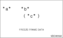
• Data stored at the time of failure occurred is shown on display.
• Each time a failure occurs, the latest information is stored in the freeze frame data in memory.
• 1 freeze frame data is stored.
• If a freeze frame data is not properly stored in memory (due to a drop in VDCCM power supply, etc.), a DTC suffixed with a question mark “?” appears on the Subaru Select Monitor display. This shows it may be an unreliable reading.
|
*a*: |
DTC (2 digits) |
|
*b*: |
Trouble contents |
|
*c*: |
Detail DTC (4 digits) |
|
Display |
Contents to be monitored |
|
FR Wheel Speed |
Wheel speed detected by the front ABS wheel speed sensor RH is displayed in km/h. |
|
FL Wheel Speed |
Wheel speed detected by the front ABS wheel speed sensor LH is displayed in km/h. |
|
RR Wheel Speed |
Wheel speed detected by the rear ABS wheel speed sensor RH is displayed in km/h. |
|
RL Wheel Speed |
Wheel speed detected by the rear ABS wheel speed sensor LH is displayed in km/h. |
|
Steering Angle Sensor |
Steering wheel angle detected by steering angle sensor is displayed. |
|
Yaw Rate Sensor |
Vehicle angular speed detected by the yaw rate sensor is converted and displayed in volts. |
|
Lateral G Sensor |
Vehicle lateral direction acceleration detected by lateral G sensor is converted and displayed in volts. |
|
Primary Pressure Sensor |
Brake fluid pressure detected by the primary pressure sensor is converted and displayed in volts. |
|
Secondary Pressure Sensor |
Brake fluid pressure detected by the secondary pressure sensor is converted and displayed in volts. |
|
Vehicle Speed |
The vehicle speed is displayed. |
|
Required Torque |
Engine torque required by the driver is displayed. |
|
Current Torque |
Current engine torque is displayed. |
|
Target Torque |
The target torque is displayed. |
|
Acceleration Opening Angle |
Acceleration opening is displayed. |
|
Engine Speed |
Engine speed is displayed. |
|
Gear Position |
Gear position is displayed. |
|
IG Power Supply Voltage |
Voltage supplied to VDC control module is displayed. |
|
ABS Warning Light |
ON/OFF condition of the ABS warning light is displayed. |
|
EBD Warning Light |
ON/OFF condition of the EBD warning light is displayed. |
|
VDC Warning Light |
ON/OFF condition of the VDC warning light/VDC OFF indicator light is displayed. (ON is displayed when there is a VDC failure.) |
|
VDC OFF Light |
ON/OFF condition of the VDC warning light/VDC OFF indicator light is displayed. (ON/OFF is displayed by operating the VDC OFF switch and EAM signal.) |
|
VDC Operation Light |
ON/OFF condition of VDC OFF indicator light is displayed. |
|
Valve Relay Signal |
The valve relay operating condition is displayed. |
|
Motor Relay Driving Vibration |
The motor relay operating condition is displayed. |
|
Motor Relay Monitor |
The motor relay operating condition is displayed. |
|
Decreasing Required Torque |
Engine torque decrease request is displayed. |
|
EAM Signal |
Engine control command signal is displayed. |
|
VDC O Control Flag |
VDC operation condition (over-steering) is displayed. |
|
VDC U Control Flag |
VDC operation condition (under-steering) is displayed. |
|
ABS Control Flag |
ABS operating condition is displayed. |
|
VDC OK B Signal |
VDC sensor normal flag |