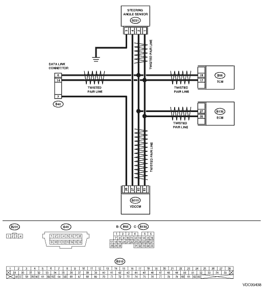
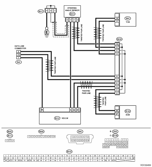
1.CHECK HARNESS BETWEEN VDCCM, STEERING ANGLE SENSOR AND TCM.
1) Turn the ignition switch to OFF.
2) Disconnect the connectors from the VDCCM, TCM, ECM and the steering angle sensor.
3) Measure the resistance between the VDCCM, TCM, ECM and the steering angle sensor.
Connector & terminal
(B310) No. 83 — (B55) No. 18:
(B310) No. 81 — (B55) No. 17:
(B310) No. 83 — (B231) No. 2:
(B310) No. 81 — (B231) No. 1:
(B310) No. 83 — (B136) No. 27:
(B310) No. 81 — (B136) No. 35:
|
Is the resistance less than 0.5 Ω?
|
|
|
2.CHECK HARNESS BETWEEN STEERING ANGLE SENSOR AND TCM.
Measure the resistance between TCM and the steering angle sensor.
Connector & terminal
(B55) No. 18 — (B231) No. 2:
(B55) No. 17 — (B231) No. 1:
|
Is the resistance less than 0.5 Ω?
|
|
Repair or replace the harness connector between the TCM and the steering angle sensor.
|
3.CHECK HARNESS BETWEEN STEERING ANGLE SENSOR AND ECM.
Measure the resistance between ECM and the steering angle sensor.
Connector & terminal
(B231) No. 2 — (B136) No. 27:
(B231) No. 1 — (B136) No. 35:
|
Is the resistance less than 0.5 Ω?
|
Repair or replace the harness connector between the VDCCM and ECM.
|
Repair or replace the harness connector between the steering angle sensor and ECM.
|
4.CHECK GROUND SHORT CIRCUIT OF HARNESS.
Measure the resistance between VDCCM and chassis ground.
Connector & terminal
(B310) No. 83 — Chassis ground:
(B310) No. 81 — Chassis ground:
|
Is the resistance 1 MΩ or more?
|
|
Repair or replace the harness connectors between the VDCCM, TCM, ECM and the steering angle sensor.
|
5.CHECK BATTERY SHORT OF HARNESS.
Measure the voltage between VDCCM and chassis ground.
Connector & terminal
(B310) No. 83 (+) — Chassis ground (−):
(B310) No. 81 (+) — Chassis ground (−):
|
Is the voltage less than 0.5 V?
|
|
Repair or replace the harness connectors between the VDCCM, TCM, ECM and the steering angle sensor.
|
6.CHECK BATTERY SHORT OF HARNESS.
1) Turn the ignition switch to ON.
2) Measure the voltage between VDCCM and chassis ground.
Connector & terminal
(B310) No. 83 (+) — Chassis ground (−):
(B310) No. 81 (+) — Chassis ground (−):
|
Is the voltage less than 0.5 V?
|
|
Repair or replace the harness connectors between the VDCCM, TCM, ECM and the steering angle sensor.
|
7.CHECK STEERING ANGLE SENSOR.
1) Turn the ignition switch to OFF.
2) Connect the connector to the steering angle sensor.
3) Measure the resistance between the VDCCM connector terminals.
|
Is the resistance 120±6 Ω?
|
|
|
8.CHECK POOR CONTACT OF CONNECTOR.
|
Is there poor contact in steering angle sensor?
|
Repair or replace the steering angle sensor connector.
|
Replace the steering angle sensor.
|
9.CHECK VDCCM.
1) Connect the connector to VDCCM.
2) Disconnect the connector from steering angle sensor.
3) Measure the resistance between connector terminals of the steering angle sensor.
|
Is the resistance 1 MΩ or more?
|
|
|
10.CHECK POOR CONTACT OF CONNECTOR.
|
Is there poor contact in the VDCCM?
|
Repair or replace the VDCCM connector.
|
|
11.CHECK TCM.
1) Connect the connector to TCM.
2) Disconnect the connectors from VDCCM.
3) Measure the resistance between the steering angle sensor terminals.
|
Is the resistance 1 MΩ or more?
|
|
|
12.CHECK POOR CONTACT OF CONNECTOR.
|
Is there poor contact in the TCM?
|
Repair or replace the TCM connector.
|
|
13.CHECK ECM.
1) Connect the connector to ECM.
2) Disconnect the connector from TCM.
3) Measure the resistance between the steering angle sensor terminals.
|
Is the resistance 120±6 Ω?
|
|
|
14.CHECK POOR CONTACT OF CONNECTOR.
|
Is there poor contact in ECM?
|
Repair or replace the ECM connector.
|
|
15.CHECK VDCCM.
1) Connect all connectors.
3) Perform the Inspection Mode.
|
Are other DTCs displayed?
|
|
Temporary poor contact occurs.
|
16.CHECK ANY OTHER DTC ON DISPLAY.
|
Is the same DTC displayed again?
|
|
Go to the diagnosis corresponding to the DTC.
|
17.CHECK AT SYSTEM DTC DISPLAY.
|
Is the DTC P1718 of the AT system displayed?
|
Replace the steering angle sensor.
|
|