1.CHECK OUTPUT OF ABS WHEEL SPEED SENSOR USING SUBARU SELECT MONITOR.
1) Select {Current Data Display & Save} in Subaru Select Monitor.
2) Read the ABS wheel speed sensor output corresponding to the faulty area in the Subaru Select Monitor data display mode.
|
Does the speed indicated on the display change in response to the speedometer reading during acceleration or deceleration when the steering wheel is in the straight-ahead position?
|
|
|
2.CHECK POOR CONTACT OF CONNECTOR.
Turn the ignition switch to OFF.
|
Is there poor contact in connectors between VDCCM and ABS wheel speed sensor?
|
|
|
3.CHECK CAUSE OF SIGNAL NOISE.
|
Are the radio wave devices and electric components installed correctly?
|
|
Install the radio wave devices and electric components properly.
|
4.CHECK CAUSE OF SIGNAL NOISE.
|
Are causes of the noise (such as an antenna) installed near the sensor harness?
|
Install the noise sources away from the sensor harness.
|
|
5.CHECK VDCCM.
1) Connect all connectors.
3) Perform the Inspection Mode.
|
Is the same DTC displayed again?
|
Replace the VDCCM. 
|
|
6.CHECK ANY OTHER DTC ON DISPLAY.
|
Are other DTCs displayed?
|
Temporary noise interference occurs.
|
Go to the diagnosis corresponding to the DTC.
|
7.CHECK INSTALLATION OF ABS WHEEL SPEED SENSOR.
|
Is the ABS wheel speed sensor installation bolt tightened to 33±10 N·m (3.4±1.0 kgf-m, 24.6±7.2 ft-lb)?
|
|
Tighten the ABS wheel speed sensor installation bolts.
|
8.CHECK ABS WHEEL SPEED SENSOR CLEARANCE.
Measure the clearance between the tone wheel and protrusion around the wheel.
|
Is the clearance within the following? Front wheel: 0.3 — 0.8 mm (0.012 — 0.031 in); Rear wheel: 0.7 — 1.2 mm (0.0276 — 0.0472 in)
|
|
Adjust the clearance.
NOTE:
Adjust the gap using spacers (Part No. 26755AA000). If spacers cannot correct the gap, replace the worn sensor or worn tone wheel.
|
9.CHECK USING OSCILLOSCOPE.
|
Is an oscilloscope available?
|
|
|
10.CHECK ABS WHEEL SPEED SENSOR SIGNAL.
1) Jack up the vehicle until all four wheels are off the ground.
2) Turn the ignition switch to OFF.
3) Remove the VDCCM connector cover.
4) Connect the oscilloscope to the connector.
5) Turn the ignition switch to ON.
6) Start the wheel, and measure the voltage at the specified frequency.
NOTE:
When this inspection is completed, VDCCM may record DTC 29.
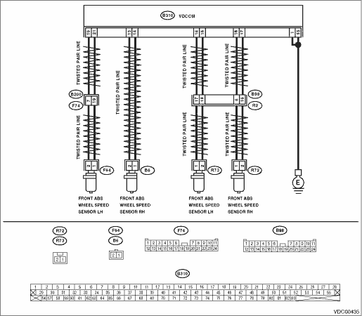
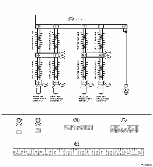
Connector & terminal
DTC 22
(B310) No. 14 (+) — No. 13 (−):
DTC 24
(B310) No. 21 (+) — No. 19 (−):
DTC 26
(B310) No. 18 (+) — No. 17 (−):
DTC 28
(B310) No. 16 (+) — No. 15 (−):
|
Is the oscilloscope pattern the same waveform as shown in the figure?
|
|
|
11.CHECK CONTAMINATION OF ABS WHEEL SPEED SENSOR OR TONE WHEEL.
Remove the disc rotor from the hub according to the DTC.
|
Is the ABS wheel speed sensor piece or the tone wheel contaminated by dirt or other foreign matter?
|
Thoroughly remove dirt or other foreign matter.
|
|
12.CHECK DAMAGE OF ABS WHEEL SPEED SENSOR OR TONE WHEEL.
|
Is there breakage or damage in the protrusion of the ABS wheel speed sensor or the tone wheel?
|
|
|
13.CHECK TONE WHEEL RUNOUT.
Measure the tone wheel runout.
|
Is the runout less than 0.05 mm (0.0020 in)?
|
|
Repair the tone wheel. Front: Rear:
|
14.CHECK RESISTANCE OF THE ABS WHEEL SPEED SENSOR.
1) Turn the ignition switch to OFF.
2) Disconnect the connector from the ABS wheel speed sensor.
3) Measure the resistance between ABS wheel speed sensor connector terminals.
|
Is the resistance as shown below? Front: 1.0 — 1.5 kΩ, Rear: 1.025 — 1.265 kΩ
|
|
Replace the ABS wheel speed sensor. Front: Rear:
|
15.CHECK GROUND SHORT OF ABS WHEEL SPEED SENSOR.
Measure the resistance between ABS wheel speed sensor and chassis ground.
Terminals
Front RH No. 1 — Chassis ground:
Front LH No. 1 — Chassis ground:
Rear RH No. 1 — Chassis ground:
Rear LH No. 1 — Chassis ground:
|
Is the resistance 1 MΩ or more?
|
|
Replace the ABS wheel speed sensor. Front: Rear:
|
16.CHECK HARNESS CONNECTOR BETWEEN VDCCM AND ABS WHEEL SPEED SENSOR.
1) Connect the connector to the ABS wheel speed sensor.
2) Disconnect the connectors from VDCCM.
3) Measure the resistance between the VDCCM connector terminals.
Connector & terminal
DTC 22
(B310) No. 14 — No. 13:
DTC 24
(B310) No. 21 — No. 19:
DTC 26
(B310) No. 18 — No. 17:
DTC 28
(B310) No. 16 — No. 15:
|
Is the resistance as shown below? Front: 1.0 — 1.5 kΩ, Rear: 1.025 — 1.265 kΩ
|
|
Repair the harness connector between VDCCM and ABS wheel speed sensor.
|
17.CHECK GROUND SHORT CIRCUIT OF HARNESS.
Measure the resistance between VDCCM connector and chassis ground.
Connector & terminal
DTC 22
(B310) No. 14 — Chassis ground:
DTC 24
(B310) No. 21 — Chassis ground:
DTC 26
(B310) No. 18 — Chassis ground:
DTC 28
(B310) No. 16 — Chassis ground:
|
Is the resistance 1 MΩ or more?
|
|
Repair the harness connector between VDCCM and ABS wheel speed sensor.
|
18.CHECK GROUND CIRCUIT OF VDCCM.
Measure the resistance between VDCCM and chassis ground.
Connector & terminal
(B310) No. 1 — Chassis ground:
(B310) No. 55 — Chassis ground:
|
Is the resistance less than 0.5 Ω?
|
|
Repair the VDCCM ground harness.
|
19.CHECK POOR CONTACT OF CONNECTOR.
|
Is there poor contact in connectors between VDCCM and ABS wheel speed sensor?
|
|
|
20.CHECK CAUSE OF SIGNAL NOISE.
|
Are the radio wave devices and electric components installed correctly?
|
|
Install the radio wave devices and electric components properly.
|
21.CHECK CAUSE OF SIGNAL NOISE.
|
Are causes of the noise (such as an antenna) installed near the sensor harness?
|
Install the noise sources away from the sensor harness.
|
|
22.CHECK VDCCM.
1) Connect all connectors.
3) Perform the Inspection Mode.
|
Is the same DTC displayed again?
|
Replace the VDCCM.
|
|
23.CHECK ANY OTHER DTC ON DISPLAY.
|
Are other DTCs displayed?
|
Go to the diagnosis corresponding to the DTC.
|
Temporary noise interference occurs.
|