1.CHECK DRIVING ROAD.
Interview whether the vehicle was driven on the road with banks or sandy surface.
|
Was the vehicle driven on the road with banks or sandy surface?
|
If driven on the road with banks or sandy surface, the VDCCM stores the DTC occasionally.
|
|
2.CHECK YAW RATE & LATERAL G SENSOR INSTALLATION.
Check the yaw rate & lateral G sensor installation.
|
Is the yaw rate & lateral G sensor tightened securely?
|
|
Tighten the yaw rate & lateral G sensor securely.
|
3.CHECK YAW RATE & LATERAL G SENSOR POWER SUPPLY.
1) Turn the ignition switch to OFF.
2) Disconnect the connector from yaw rate & lateral G sensor.
3) Turn the ignition switch to ON.
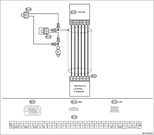
4) Measure the voltage between yaw rate & lateral sensor and the chassis ground.
Connector & terminal
(B257) No. 3 (+) — Chassis ground (−):
|
Is the voltage 10 — 15 V?
|
|
|
4.CHECK VDCCM OUTPUT VOLTAGE.
1) Turn the ignition switch to OFF.
2) Disconnect the connectors from VDCCM.
3) Remove the VDCCM connector cover. 
4) Connect the connector to the VDCCM.
5) Turn the ignition switch to ON.
6) Measure the voltage between VDCCM and chassis ground.
Connector & terminal
(B310) No. 50 (+) — Chassis ground (−):
|
Is the voltage 10 — 15 V?
|
Repair the harness between yaw rate & lateral G sensor and VDCCM.
|
|
5.CHECK POOR CONTACT OF CONNECTOR.
|
Is there poor contact in connector between yaw rate & lateral G sensor?
|
Repair or replace the VDCCM connector.
|
Replace the VDCCM.
|
6.CHECK YAW RATE & LATERAL G SENSOR GROUND CIRCUIT.
Measure the resistance between the yaw rate & lateral G sensor and the chassis ground.
Connector & terminal
(B257) No. 6 — Chassis ground:
|
Is the resistance less than 0.5 Ω?
|
|
|
7.CHECK GROUND CIRCUIT OF VDCCM.
1) Disconnect the connectors from VDCCM.
2) Remove the VDCCM connector cover.
3) Connect the connector to the VDCCM.
4) Measure the resistance between VDCCM and chassis ground.
Connector & terminal
(B310) No. 64 — Chassis ground:
|
Is the resistance less than 0.5 Ω?
|
Repair the harness between yaw rate & lateral G sensor and VDCCM.
|
|
8.CHECK POOR CONTACT OF CONNECTOR.
|
Is there poor contact in the VDCCM connector?
|
Repair or replace the VDCCM connector.
|
Replace the VDCCM.
|
9.CHECK YAW RATE & LATERAL G SENSOR HARNESS.
1) Disconnect the connectors from VDCCM.
2) Measure the resistance between VDCCM and yaw rate & lateral G sensor.
Connector & terminal
(B310) No. 65 — (B257) No. 4:
(B310) No. 66 — (B257) No. 1:
(B310) No. 67 — (B257) No. 2:
|
Is the resistance less than 0.5 Ω?
|
|
Repair the harness between yaw rate & lateral G sensor and VDCCM.
|
10.CHECK GROUND SHORT CIRCUIT OF HARNESS.
Measure the resistance between VDCCM and chassis ground.
Connector & terminal
(B310) No. 65 — Chassis ground:
(B310) No. 66 — Chassis ground:
(B310) No. 67 — Chassis ground:
|
Is the resistance 1 MΩ or more?
|
|
Repair the harness between yaw rate & lateral G sensor and VDCCM.
|
11.CHECK BATTERY SHORT OF HARNESS.
Measure the voltage between VDCCM and chassis ground.
Connector & terminal
(B310) No. 65 (+) — Chassis ground (−):
(B310) No. 66 (+) — Chassis ground (−):
(B310) No. 67 (+) — Chassis ground (−):
|
Is the voltage less than 0.5 V?
|
|
Repair the harness between yaw rate & lateral G sensor and VDCCM.
|
12.CHECK BATTERY SHORT OF HARNESS.
1) Turn the ignition switch to ON.
2) Measure the voltage between VDCCM and chassis ground.
Connector & terminal
(B310) No. 65 (+) — Chassis ground (−):
(B310) No. 66 (+) — Chassis ground (−):
(B310) No. 67 (+) — Chassis ground (−):
|
Is the voltage less than 0.5 V?
|
|
Repair the harness between yaw rate & lateral G sensor and VDCCM.
|
13.CHECK YAW RATE & LATERAL G SENSOR.
1) Turn the ignition switch to OFF.
2) Install the yaw rate & lateral G sensor to the body.
3) Connect all connectors.
4) Turn the ignition switch to ON.
5) Measure the voltage between yaw rate & lateral G sensor connector terminals.
Connector & terminal
(B310) No. 66 (+) — No. 64 (−):
|
Is the voltage 2.1 — 2.9 V?
|
Replace the VDCCM.
|
Replace the yaw rate & lateral G sensor.
|