1.CHECK GROUND CIRCUIT OF PRESSURE SENSOR.
1) Turn the ignition switch to OFF.
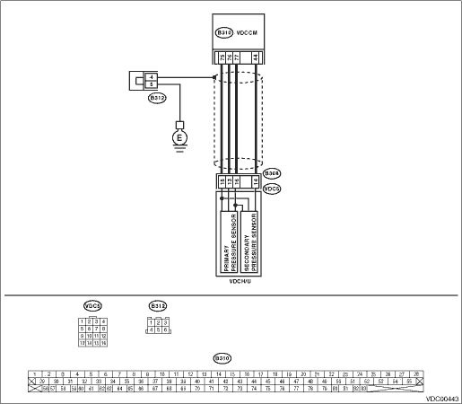
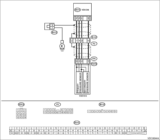
2) Disconnect the connectors (B368) (LHD model) and (F91) (RHD model) from VDCH/U.
3) Measure the resistance between VDCH/U connector and chassis ground.
Connector & terminal
LHD
(B368) No. 15 — Chassis ground:
RHD
(F91) No. 15 — Chassis ground:
|
Is the resistance less than 0.5 Ω?
|
|
|
2.CHECK GROUND CIRCUIT OF VDCCM.
1) Disconnect the connectors from VDCCM.
2) Remove the cover from VDCCM. 
3) Connect the connector to the VDCCM.
4) Measure the resistance between VDCCM and chassis ground.
Connector & terminal
(B310) No. 75 — Chassis ground:
|
Is the resistance less than 0.5 Ω?
|
Replace the harness between VDCH/U and VDCCM.
|
|
3.CHECK POOR CONTACT OF CONNECTOR.
|
Is there poor contact in the VDCCM connector?
|
Repair or replace the VDCCM connector.
|
Replace the VDCCM.
|
4.CHECK POWER SUPPLY FOR PRESSURE SENSOR.
NOTE:
When performing this inspection, DTC 51 VALVE RELAY MALFUNCTION is stored. However, this does not indicate a malfunction of valve relay.
1) Turn the ignition switch to ON.
2) Measure the voltage between VDCH/U connector terminals.
Connector & terminal
LHD
(B368) No. 16 (+) — No. 15 (−):
RHD
(F91) No. 16 (+) — No. 15 (−):
|
Is the voltage 4.75 — 5.25 V?
|
|
|
5.CHECK VDCCM POWER SUPPLY.
1) Turn the ignition switch to OFF.
2) Disconnect the connectors from VDCCM.
3) Remove the cover from VDCCM.
4) Connect the connector to the VDCCM.
5) Turn the ignition switch to ON.
6) Measure the voltage between VDCCM connector terminals.
Connector & terminal
(B310) No. 77 (+) — No. 75 (−):
|
Is the voltage 4.75 — 5.25 V?
|
Repair the harness between VDCH/U and VDCCM.
|
|
6.CHECK POOR CONTACT OF CONNECTOR.
|
Is there poor contact in the VDCCM connector?
|
Repair or replace the VDCCM connector.
|
Replace the VDCCM.
|
7.CHECK GROUND SHORT CIRCUIT OF HARNESS.
1) Turn the ignition switch to OFF.
2) Disconnect the connectors from VDCCM.
3) Measure the resistance between VDCH/U connector and chassis ground.
Connector & terminal
LHD
(B368) No. 13 — Chassis ground:
RHD
(F91) No. 13 — Chassis ground:
|
Is the resistance 1 MΩ or more?
|
|
Repair the harness between VDCH/U and VDCCM.
|
8.CHECK BATTERY SHORT OF HARNESS.
Measure the voltage between VDCH/U connector and chassis ground.
Connector & terminal
LHD
(B368) No. 13 (+) — Chassis ground (−):
RHD
(F91) No. 13 (+) — Chassis ground (−):
|
Is the voltage less than 0.5 V?
|
|
Repair the harness between VDCH/U and VDCCM.
|
9.CHECK BATTERY SHORT OF HARNESS.
1) Turn the ignition switch to ON.
2) Measure the voltage between VDCH/U connector and chassis ground.
Connector & terminal
LHD
(B368) No. 13 (+) — Chassis ground (−):
RHD
(F91) No. 13 (+) — Chassis ground (−):
|
Is the voltage less than 0.5 V?
|
|
Repair the harness between VDCH/U and VDCCM.
|
10.CHECK INPUT VOLTAGE OF PRESSURE SENSOR.
1) Turn the ignition switch to OFF.
2) Disconnect the connectors from VDCCM.
3) Remove the cover from VDCCM.
4) Connect the connector to the VDCCM.
5) Connect all connectors.
6) Turn the ignition switch to ON.
7) Do not depress the brake pedal.
8) Measure the voltage between VDCCM connector terminals.
Connector & terminal
(B310) No. 76 (+) — No. 75 (−):
|
Is the voltage 0.48 — 0.72 V?
|
|
Replace the VDCH/U.
|
11.CHECK POOR CONTACT OF CONNECTOR.
|
Is there poor contact in connectors between VDCCM and pressure sensor?
|
|
|
12.CHECK VDCCM.
1) Connect all connectors.
3) Perform the Inspection Mode.
|
In the current diagnosis, is the same DTC displayed again?
|
Replace the VDCCM.
|
|
13.CHECK ANY OTHER DTC ON DISPLAY.
|
Are other DTCs displayed?
|
Go to the diagnosis corresponding to the DTC.
|
Temporary poor contact occurs.
|