1.CHECK INPUT VOLTAGE OF ABSCM&H/U.
1) Turn the ignition switch to OFF.
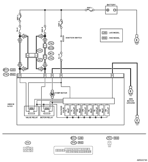
2) Disconnect the ABSCM&H/U connectors.
3) Run the engine at idle.
4) Measure the voltage between ABSCM&H/U connector and chassis ground.
Connector & terminal
LHD model
(B301) No. 18 (+) — Chassis ground (−):
(B301) No. 14 (+) — Chassis ground (−):
RHD model
(F49) No. 18 (+) — Chassis ground (−):
(F49) No. 14 (+) — Chassis ground (−):
|
Is the voltage 10 — 15 V?
|
|
Repair the harness connector between battery and ABSCM&H/U.
|
2.CHECK THE ABSCM&H/U GROUND CIRCUIT.
1) Turn the ignition switch to OFF.
2) Measure the resistance between the ABSCM&H/U connector and chassis ground.
Connector & terminal
LHD model
(B301) No. 15 — Chassis ground:
RHD model
(F49) No. 15 — Chassis ground:
|
Is the resistance less than 0.5 Ω?
|
|
Repair the ABSCM&H/U ground harness.
|
3.CHECK VALVE RELAY IN ABSCM&H/U.
Measure the resistance between the ABSCM&H/U terminals.
|
Is the resistance more than 1 MΩ?
|
|
Replace the ABSCM only. 
|
4.CHECK POOR CONTACT IN CONNECTOR.
|
Is there poor contact in connector between generator, battery and ABSCM&H/U?
|
|
|
5.CHECK ABSCM&H/U.
1) Connect all connectors.
3) Perform the Inspection Mode.
|
Is the same DTC displayed?
|
Replace the ABSCM only.
|
|
6.CHECK ANY OTHER DTC ON DISPLAY.
|
Is there any other DTC displayed?
|
Check DTC using “List of Diagnostic Trouble Code (DTC)”.
|
Temporary poor contact occurs.
|