1.CHECK GENERATOR.
2) Run the engine at idle after warming up.
3) Measure the voltage between generator terminal B and chassis ground.
Terminals
Generator B terminal (+) — Chassis ground (−):
|
Is the voltage 10 — 15 V?
|
|
|
2.CHECK BATTERY TERMINAL.
Turn the ignition switch to OFF.
|
Are the positive and negative battery terminals tightened securely?
|
|
|
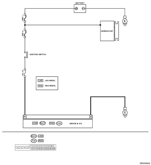
3.CHECK INPUT VOLTAGE OF ABSCM&H/U.
1) Disconnect the ABSCM&H/U connectors.
2) Run the engine at idle.
3) Operate devices such as headlights, air conditioner, defogger, etc. which produce an electrical load.
4) Measure the voltage between ABSCM&H/U connector and chassis ground.
Connector & terminal
LHD model
(B301) No. 18 (+) — Chassis ground (−):
RHD model
(F49) No. 18 (+) — Chassis ground (−):
|
Is the voltage 10 — 15 V?
|
|
Repair the ABSCM&H/U power circuit.
|
4.CHECK THE ABSCM&H/U GROUND CIRCUIT.
1) Turn the ignition switch to OFF.
2) Measure the resistance between the ABSCM&H/U connector and chassis ground.
Connector & terminal
LHD model
(B301) No. 15 — Chassis ground:
RHD model
(F49) No. 15 — Chassis ground:
|
Is the resistance less than 0.5 Ω?
|
|
Repair the ABSCM&H/U ground harness.
|
5.CHECK POOR CONTACT IN CONNECTOR.
|
Is there poor contact in connector between generator, battery and ABSCM&H/U?
|
|
|
6.CHECK ABSCM&H/U.
1) Connect all connectors.
3) Perform the Inspection Mode.
|
Is the same DTC displayed?
|
Replace the ABSCM only. 
|
|
7.CHECK ANY OTHER DTC ON DISPLAY.
|
Is there any other DTC displayed?
|
Check DTC using “List of Diagnostic Trouble Code (DTC)”.
|
Temporary poor contact occurs.
|