1.CHECK FOR LOOSENED GROUND BOLT.
Check for looseness in the ABSCM&H/U motor ground bolt.
|
Is ground bolt tightened to 13 N·m (1.3 kgf-m, 9.4 ft-lb) torque?
|
|
|
2.CHECK INPUT VOLTAGE OF ABSCM&H/U.
1) Turn the ignition switch to OFF.
2) Disconnect the ABSCM&H/U connectors.
3) Turn the ignition switch to ON.
4) Measure the voltage between ABSCM&H/U connector and chassis ground.
Connector & terminal
LHD model
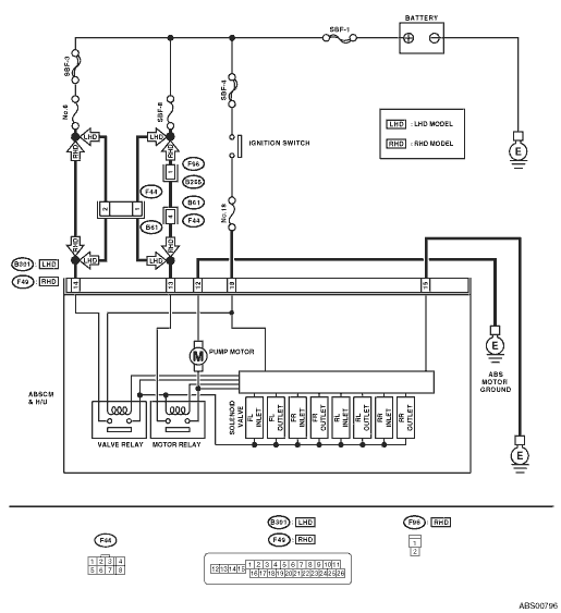
(B301) No. 13 (+) — Chassis ground (−):
RHD model
(F49) No. 13 (+) — Chassis ground (−):
|
Is the voltage 10 — 15 V?
|
|
Repair the harness connector between battery and ABSCM&H/U.
|
3.CHECK GROUND CIRCUIT OF MOTOR.
1) Turn the ignition switch to OFF.
2) Measure the resistance between the ABSCM&H/U connector and chassis ground.
Connector & terminal
LHD model
(B301) No. 12 — Chassis ground:
RHD model
(F49) No. 12 — Chassis ground:
|
Is the resistance less than 0.5 Ω?
|
|
Repair the ABSCM&H/U ground harness.
|
4.CHECK INPUT VOLTAGE OF ABSCM&H/U.
1) Run the engine at idle.
2) Measure the voltage between ABSCM&H/U connector and chassis ground.
Connector & terminal
LHD model
(B301) No. 18 (+) — Chassis ground (−):
RHD model
(F49) No. 18 (+) — Chassis ground (−):
|
Is the voltage 10 — 15 V?
|
|
Repair the harness connector between battery, ignition switch and ABSCM&H/U.
|
5.CHECK THE ABSCM&H/U GROUND CIRCUIT.
1) Turn the ignition switch to OFF.
2) Measure the resistance between the ABSCM&H/U connector and chassis ground.
Connector & terminal
LHD model
(B301) No. 15 — Chassis ground:
RHD model
(F49) No. 15 — Chassis ground:
|
Is the resistance less than 0.5 Ω?
|
|
Repair the ABSCM&H/U ground harness.
|
6.CHECK POOR CONTACT IN CONNECTOR.
Turn the ignition switch to OFF.
|
Is there poor contact in connector between generator, battery and ABSCM&H/U?
|
|
|
7.CHECK ABSCM&H/U.
1) Connect all connectors.
3) Perform the Inspection Mode.
|
Is the same DTC displayed?
|
Replace the ABSCM&H/U. 
|
|
8.CHECK ANY OTHER DTC ON DISPLAY.
|
Is there any other DTC displayed?
|
Check DTC using “List of Diagnostic Trouble Code (DTC)”.
|
Temporary poor contact occurs.
NOTE:
Though the ABS warning light remains on at this time, this is normal. Drive the vehicle at more than 12 km/h (7 MPH) in order to turn ABS warning light off. Be sure to drive the vehicle and check that the warning light goes off.
|