1.WHETHER A WHEEL TURNED FREELY OR NOT.
|
Have the wheels spun free of load when the vehicle is lifted up, or during driving on a rough road?
|
ABS is normal. Erase the memory.
|
|
2.CHECK OUTPUT OF G SENSOR USING SUBARU SELECT MONITOR.
1) Select {Current Data Display & Save} in Subaru Select Monitor.
2) Read the G sensor output on Subaru Select Monitor.
|
Is the reading indicated on display −1.2 — 1.2 m/s when the G sensor is horizontal?
|
|
|
3.CHECK POOR CONTACT IN CONNECTOR.
|
Is there poor contact in connectors between ABSCM&H/U and G sensor?
|
|
|
4.CHECK ABSCM&H/U.
1) Connect all connectors.
3) Perform the Inspection Mode.
|
Is the same DTC displayed?
|
Replace the ABSCM only. 
|
|
5.CHECK ANY OTHER DTC ON DISPLAY.
|
Is there any other DTC displayed?
|
Check DTC using “List of Diagnostic Trouble Code (DTC)”.
|
Temporary poor contact occurs.
|
6.CHECK INPUT VOLTAGE OF G SENSOR.
1) Turn the ignition switch to OFF.
2) Remove the console box.
3) Remove the G sensor from vehicle. (Do not disconnect the connector.)
4) Turn the ignition switch to ON.
5) Measure the voltage between G sensor connector terminals.
Connector & terminal
(B292) No. 1 (+) — No. 3 (−):
|
Is the voltage 4.75 — 5.25 V?
|
|
Repair the harness connector between the G sensor and ABSCM&H/U.
|
7.CHECK OPEN CIRCUIT IN G SENSOR OUTPUT HARNESS AND GROUND HARNESS.
1) Turn the ignition switch to OFF.
2) Disconnect the ABSCM&H/U connectors.
3) Measure the resistance between ABSCM&H/U connector terminals.
Connector & terminal
LHD model
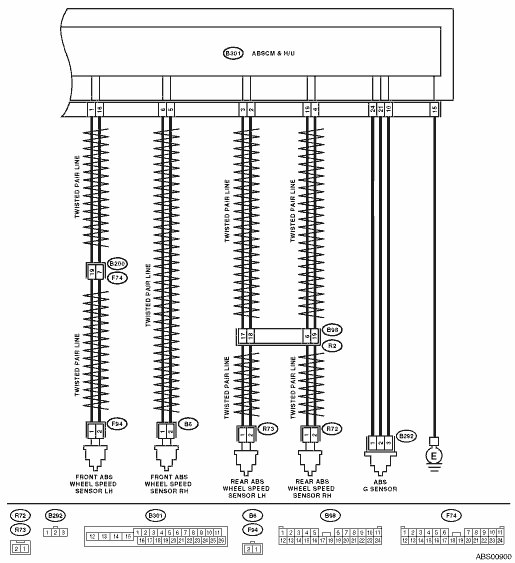
(B301) No. 21 — No. 10:
RHD model
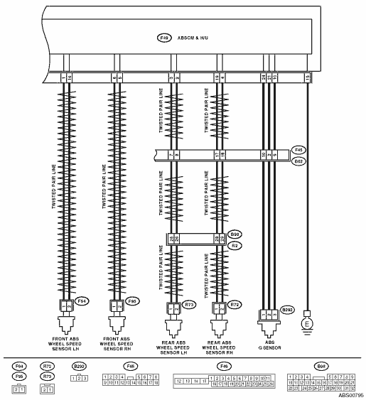
(F49) No. 21 — No. 10:
|
Is the resistance between 3.6 — 3.8 kΩ?
|
|
Repair the harness connector between the G sensor and ABSCM&H/U.
|
8.CHECK GROUND SHORT IN G SENSOR OUTPUT HARNESS.
1) Disconnect the connector from G sensor.
2) Measure the resistance between the ABSCM&H/U connector and chassis ground.
Connector & terminal
LHD model
(B301) No. 21 — Chassis ground:
RHD model
(F49) No. 21 — Chassis ground:
|
Is the resistance more than 1 MΩ?
|
|
Repair the harness between the G sensor and ABSCM&H/U.
|
9.CHECK G SENSOR.
1) Connect the connector to G sensor.
2) Connect the connector to ABSCM&H/U.
3) Turn the ignition switch to ON.
4) Measure the voltage between G sensor connector terminals.
Connector & terminal
(B292) No. 2 (+) — No. 3 (−):
|
Is the voltage 2.1 — 2.5 V when G sensor is in horizontal position?
|
|
Replace G sensor.
|
10.CHECK G SENSOR.
Measure the voltage between G sensor connector terminals.
Connector & terminal
(B292) No. 2 (+) — No. 3 (−):
|
Is the voltage 3.6 — 4.1 V when the G sensor is inclined forward to 90°?
|
|
Replace G sensor.
|
11.CHECK G SENSOR.
Measure the voltage between G sensor connector terminals.
Connector & terminal
(B292) No. 2 (+) — No. 3 (−):
|
Is the voltage 0.5 — 1.0 V when G sensor is inclined back 90°?
|
|
Replace G sensor.
|
12.CHECK POOR CONTACT IN CONNECTOR.
Turn the ignition switch to OFF.
|
Is there poor contact in connectors between ABSCM&H/U and G sensor?
|
|
|
13.CHECK ABSCM&H/U.
1) Connect all connectors.
3) Perform the Inspection Mode.
|
Is the same DTC displayed?
|
Replace the ABSCM only.
|
|
14.CHECK ANY OTHER DTC ON DISPLAY.
|
Is there any other DTC displayed?
|
Check DTC using “List of Diagnostic Trouble Code (DTC)”.
|
Temporary poor contact occurs.
|