1.CHECK ANY OTHER DTC ON DISPLAY.
|
Are DTCs P0031 and P0037 displayed together on the Subaru Select Monitor?
|
|
|
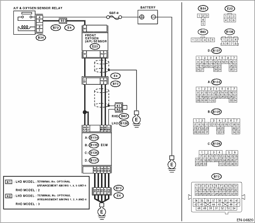
2.CHECK POWER SUPPLY TO FRONT OXYGEN (A/F) SENSOR.
1) Turn the ignition switch to OFF.
2) Disconnect the connector from front oxygen (A/F) sensor.
3) Turn the ignition switch to ON.
4) Measure the voltage between front oxygen (A/F) sensor connector and engine ground.
Connector & terminal
(E23) No. 6 (+) — Engine ground (−):
|
Is the voltage 10 V or more?
|
|
Repair the power supply line.
NOTE:
In this case, repair the following item:
• Open circuit of harness between main relay and front oxygen (A/F) sensor connector
• Poor contact in front oxygen (A/F) sensor connector
• Poor contact of main relay connector
|
3.CHECK GROUND CIRCUIT FOR ECM.
Measure the resistance of harness between ECM connector and chassis ground.
Connector & terminal
(B134) No. 5 — Chassis ground:
(B137) No. 7 — Chassis ground:
(B137) No. 1 — Chassis ground:
(B137) No. 2 — Chassis ground:
(B137) No. 3 — Chassis ground:
|
Is the resistance less than 5 Ω?
|
|
Repair the harness and connector.
NOTE:
In this case, repair the following item:
• Open circuit of harness between ECM and engine ground terminal
• Poor contact in ECM connector
• Poor contact of coupling connector
|
4.CHECK CURRENT DATA.
2) Read the data of front oxygen (A/F) sensor heater current using Subaru Select Monitor.
NOTE:
For detailed operation procedure, refer to “READ CURRENT DATA FOR ENGINE”. 
|
Is the current 0.2 A or more?
|
Repair the poor contact of connector.
NOTE:
In this case, repair the following item:
• Poor contact in front oxygen (A/F) sensor connector
• Poor contact in ECM connector
|
|
5.CHECK INPUT SIGNAL OF ECM.
1) Start and idle the engine.
2) Measure the voltage between ECM connector and chassis ground.
Connector & terminal
(B136) No. 2 (+) — Chassis ground (−):
(B136) No. 3 (+) — Chassis ground (−):
|
Is the voltage less than 1 V?
|
|
|
6.CHECK OUTPUT SIGNAL OF ECM.
Measure the voltage between ECM connector and chassis ground.
Connector & terminal
(B136) No. 2 (+) — Chassis ground (−):
(B136) No. 3 (+) — Chassis ground (−):
|
Does the voltage change by shaking the harness and connector of ECM while monitoring the value on voltage meter?
|
Repair the poor contact of ECM connector.
|
|
7.CHECK FRONT OXYGEN (A/F) SENSOR.
1) Turn the ignition switch to OFF.
2) Measure the resistance between front oxygen (A/F) sensor connector terminals.
|
Is the resistance less than 10 Ω?
|
Repair the harness and connector.
NOTE:
In this case, repair the following item:
• Open or ground short circuit of harness between front oxygen (A/F) sensor and ECM connector
• Poor contact in front oxygen (A/F) sensor connector
• Poor contact in ECM connector
|
Replace the front oxygen (A/F) sensor.
|