DTC DETECTING CONDITION:
Input signal circuit to ATF temperature sensor is open or shorted.
TROUBLE SYMPTOM:
Excessive shift shock
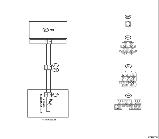
WIRING DIAGRAM:

| STEP | CHECK | YES | NO |
|
Is the resistance 500 Ω or more? |
|
|
|
|
Is the resistance 1 MΩ or more? |
|
|
|
|
Does the resistance change? |
|
Replace the TCM. |
|
|
Is the resistance 1 MΩ or more? |
|
Repair the short circuit of harness between TCM and transmission harness. |
|
|
Is the resistance 500 Ω or more? |
Even if the power indicator light is blinking, the circuit is in normal condition at this time. A temporary short circuit of connector or harness may be the cause. Repair the harness or connector. |
|
|
|
1) Lift up the vehicle and place it on rigid racks. 2) Drain the automatic transmission fluid. CAUTION: Do not drain ATF until it cools down. 3) Remove the oil pan. 4) Disconnect the harness connector from control valve. 5) Measure the resistance between ATF temperature sensor connector terminals. 6) Measure the resistance between transmission connector and transmission ground. Connector & terminal (T4) No. 11 — Transmission ground: |
Is the resistance 1 MΩ or more? |
|
Replace the transmission harness. |
|
Is the resistance 1 MΩ or more? |
|
Replace the transmission harness. |
|
|
Is the resistance 500 Ω or more? |
Even if the power indicator light is blinking, the circuit is in normal condition at this time. A temporary short circuit of connector or harness may be the cause. Repair the harness or connector. |
Replace the control valve body. |
