1.CHECK HARNESS CONNECTOR BETWEEN TCM AND TRANSMISSION.
1) Turn the ignition switch to OFF.
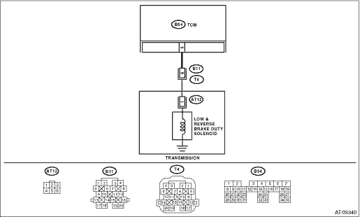
2) Disconnect the connector from transmission and TCM.
3) Measure the resistance of harness between TCM connector and transmission connector.
Connector & terminal
(B54) No. 5 — (B11) No. 6:
|
Is the resistance less than 1 Ω?
|
|
Repair the open circuit of harness between TCM and transmission connector.
|
2.CHECK HARNESS CONNECTOR BETWEEN TCM AND CHASSIS GROUND.
Measure the resistance of harness between TCM connector and chassis ground.
Connector & terminal
(B54) No. 5 — Chassis ground:
|
Is the resistance 1 MΩ or more?
|
|
Repair the short circuit of harness between TCM and transmission connector.
|
3.CHECK LOW & REVERSE BRAKE DUTY SOLENOID.
Measure the resistance between transmission connector terminals.
|
Is the resistance between 2.0 — 4.5 Ω?
|
|
|
4.CHECK OUTPUT SIGNAL FROM TCM USING SUBARU SELECT MONITOR.
1) Connect all connectors.
2) Connect the Subaru Select Monitor to the data link connector.
3) Start the engine, and turn the Subaru Select Monitor power switch to ON.
4) Warm-up the transmission until the ATF temperature exceeds approximately 80°C (176°F).
NOTE:
If the ambient temperature falls below 0°C (32°F), drive the vehicle until the ATF reaches its operating temperature.
5) Stop the engine and turn the ignition switch to ON (with engine OFF).
6) Shift the select lever to “N” range.
7) Read the data of low & reverse brake duty solenoid using Subaru Select Monitor.
NOTE:
Low & reverse brake duty solenoid is indicated in “%”.
|
Is the measured value 100%?
|
|
|
5.CHECK OUTPUT SIGNAL FROM TCM USING SUBARU SELECT MONITOR.
1) Lift up the vehicle and place it on rigid racks.
NOTE:
Raise all wheels off the floor.
2) Shift the select lever to “1” range. Slowly increase the vehicle speed up to 15 km/h (9 MPH), and then return the accelerator pedal.
NOTE:
The speed difference between front and rear wheels may illuminate the ABS warning light, but this does not indicate a malfunction. When AT control diagnosis is finished, perform the ABS or VDC clear memory of on-board diagnostics system.
3) Read the data of the low & reverse duty solenoid.
|
Is the measured value 55%?
|
Even if the power indicator light is blinking, the circuit is in normal condition at this time. A temporary poor contact of connector or harness may be the cause. Repair the harness or connector in TCM and transmission.
|
|
|
|
Is there poor contact in the low & reverse duty solenoid circuit?
|
|
Replace the TCM. 
|
7.CHECK LOW & REVERSE BRAKE DUTY SOLENOID (IN TRANSMISSION).
1) Remove the transmission connector from bracket.
2) Drain the automatic transmission fluid.
CAUTION:
Do not drain ATF until it cools down.
3) Remove the oil pan, and disconnect the connector from low & reverse brake duty solenoid.
4) Measure the resistance between low & reverse brake duty solenoid connector and transmission ground.
Connector & terminal
(AT12) No. 1 — Transmission ground:
|
Is the resistance between 2.0 — 4.5 Ω?
|
|
Replace the low & reverse brake duty solenoid.
|
8.CHECK HARNESS CONNECTOR BETWEEN TRANSMISSION AND LOW & REVERSE DUTY SOLENOID.
Measure the resistance of harness between low & reverse duty solenoid and transmission connector.
Connector & terminal
(T4) No. 6 — (AT12) No. 1:
|
Is the resistance less than 1 Ω?
|
|
Repair open circuit of harness between low & reverse brake duty solenoid and transmission connector.
|
9.CHECK HARNESS CONNECTOR BETWEEN TRANSMISSION AND LOW & REVERSE BRAKE DUTY SOLENOID.
Measure the resistance of harness between transmission connector and transmission ground.
Connector & terminal
(T4) No. 6 — Transmission ground:
|
Is the resistance 1 MΩ or more?
|
Even if the power indicator light is blinking, the circuit is in normal condition at this time. A temporary poor contact of connector or harness may be the cause. Repair harness or connector in low & reverse brake duty solenoid and transmission.
|
Repair the short circuit of the harness between the low & reverse brake duty solenoid and the transmission connector.
|