1.CHECK IGNITION POWER SUPPLY CIRCUIT.
1) Turn the ignition switch to OFF.
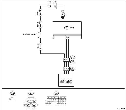
2) Disconnect the connector from rear vehicle speed sensor.
3) Measure the ignition power supply voltage between rear vehicle speed sensor connector and transmission ground.
Connector & terminal
(AT10) No. 3 (+) — Transmission ground (−):
|
Is the voltage 10 V or more?
|
|
Check harness between rear vehicle speed sensor and battery for open circuit, short or poor contact. Repair the harness if required.
|
2.CHECK HARNESS CONNECTOR BETWEEN TCM AND TRANSMISSION.
1) Turn the ignition switch to OFF.
2) Measure the resistance of harness between TCM connector and transmission connector.
Connector & terminal
(B55) No. 15 — (AT10) No. 1:
|
Is the resistance less than 1 Ω?
|
|
Repair the open circuit or poor contact of the connector in harness between TCM and rear vehicle speed sensor connector.
|
3.CHECK HARNESS CONNECTOR BETWEEN TCM AND TRANSMISSION.
Measure the resistance of harness between TCM connector and transmission connector.
Connector & terminal
(B55) No. 26 — (AT10) No. 2:
|
Is the resistance less than 1 Ω?
|
|
Repair the open circuit or poor contact of the connector in harness between TCM and rear vehicle speed sensor connector.
|
4.CHECK HARNESS CONNECTOR BETWEEN TCM AND TRANSMISSION.
Measure the resistance of harness between TCM connector and chassis ground.
Connector & terminal
(B55) No. 15 — Chassis ground:
|
Is the resistance 1 MΩ or more?
|
|
Repair the short circuit of harness between TCM and rear vehicle speed sensor connector.
|
5.CHECK HARNESS CONNECTOR BETWEEN TCM AND TRANSMISSION.
Measure the resistance of harness between TCM connector and chassis ground.
Connector & terminal
(B55) No. 26 — Chassis ground:
|
Is the resistance 1 MΩ or more?
|
|
Repair the short circuit of harness between TCM and rear vehicle speed sensor connector.
|
6.CHECK INPUT SIGNAL FOR TCM.
1) Connect the connectors to TCM and transmission.
2) Lift up the vehicle and place it on rigid racks.
NOTE:
Raise all wheels off the floor.
3) Start the engine and set vehicle in 20 km/h (12 MPH) condition.
NOTE:
The speed difference between front and rear wheels may illuminate the ABS warning light, but this does not indicate a malfunction. When AT control diagnosis is finished, perform the ABS or VDC clear memory of on-board diagnostics system. 
4) Measure the AC voltage between TCM connector terminals.
Connector & terminal
(B55) No. 26 (+) — No. 15 (−):
|
Is the voltage 2 V or more?
|
|
Replace the rear vehicle speed sensor.
|
|
|
Is there poor contact in rear vehicle speed sensor circuit?
|
|
Replace the TCM.
|