1.CHECK HARNESS CONNECTOR BETWEEN TCM AND TRANSMISSION.
1) Turn the ignition switch to OFF.
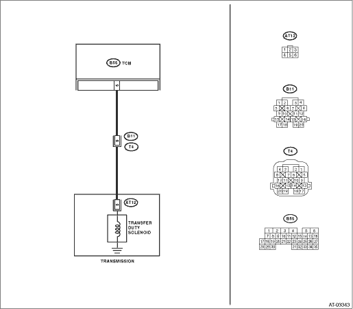
2) Disconnect the connectors from TCM and transmission.
3) Measure the resistance of harness between TCM connector and transmission connector.
Connector & terminal
(B55) No. 5 — (B11) No. 8:
|
Is the resistance less than 1 Ω?
|
|
Repair the open circuit of harness between TCM and transmission connector.
|
2.CHECK HARNESS CONNECTOR BETWEEN TCM AND TRANSMISSION.
Measure the resistance of harness connector between TCM and chassis ground.
Connector & terminal
(B55) No. 5 — Chassis ground:
|
Is the resistance 1 MΩ or more?
|
|
Repair the short circuit of harness between TCM and transmission connector.
|
3.CHECK TRANSFER DUTY SOLENOID.
Measure the resistance between transmission connector and transmission terminals.
|
Is the resistance between 2.0 — 4.5 Ω?
|
|
|
4.CHECK OUTPUT SIGNAL FROM TCM USING SUBARU SELECT MONITOR.
1) Connect the connectors to TCM and transmission.
2) Connect the Subaru Select Monitor to the data link connector.
3) Turn the ignition switch to ON (engine OFF), and turn the Subaru Select Monitor power switch to ON.
4) Shift the select lever to the “N” range, and fully close the throttle pedal. (Vehicle speed is 0 km/h (0 MPH))
5) Read the data of transfer duty solenoid using Subaru Select Monitor.
• Transfer duty solenoid is indicated in “%”.
|
Is the measured value 5%?
|
|
|
5.CHECK OUTPUT SIGNAL FROM TCM USING SUBARU SELECT MONITOR.
1) Shift the select lever to “D” range.
2) Read the data of transfer duty solenoid using Subaru Select Monitor.
• Transfer duty solenoid is indicated in “%”.
|
Is the measured value approximately 18 to 35%?
|
Even if the power indicator light is blinking, the circuit is in normal condition at this time. A temporary poor contact of connector or harness may be the cause. Repair the harness or connector in TCM and transmission.
|
|
|
|
Is there poor contact in transfer duty solenoid circuit?
|
|
Replace the TCM. 
|
7.CHECK TRANSFER DUTY SOLENOID (IN TRANSMISSION).
1) Lift up the vehicle and place it on rigid racks.
NOTE:
Raise all wheels off the floor.
2) Drain the automatic transmission fluid.
CAUTION:
Do not drain ATF until it cools down.
3) Remove the extension case, and disconnect the connector from transfer duty solenoid.
4) Measure the resistance between transfer duty solenoid connector and transmission ground.
Connector & terminal
(AT12) No. 5 — Transmission ground:
|
Is the resistance between 2.0 — 4.5 Ω?
|
|
Replace the control valve body.
|
8.CHECK HARNESS CONNECTOR BETWEEN TRANSFER DUTY SOLENOID AND TRANSMISSION.
Measure the resistance of harness between transfer duty solenoid and transmission connector.
Connector & terminal
(T4) No. 8 — (AT12) No. 5:
|
Is the resistance less than 1 Ω?
|
|
Repair the open circuit of harness between transfer duty solenoid and transmission connector.
|
9.CHECK HARNESS CONNECTOR BETWEEN TRANSFER DUTY SOLENOID AND TRANSMISSION.
Measure the resistance of harness between transmission connector and transmission ground.
Connector & terminal
(T4) No. 8 — Transmission ground:
|
Is the resistance 1 MΩ or more?
|
Even if the power indicator light is blinking, the circuit is in normal condition at this time. A temporary poor contact of connector or harness may be the cause. Repair the harness or poor contact in the transfer duty solenoid and transmission.
|
Repair short circuit of the harness between the transfer duty solenoid and transmission connector.
|