1. CHECK POWER INDICATOR LIGHT.
DIAGNOSIS:
Power indicator light circuit is open or shorted.
TROUBLE SYMPTOM:
When the ignition switch is turned to ON (engine OFF), power indicator light does not illuminate.
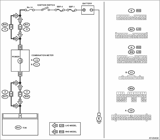
WIRING DIAGRAM:

1.CHECK POWER INDICATOR LIGHT.
Turn the ignition switch to ON (engine OFF).
|
Does the power indicator light illuminate?
|
|
|
2.CHECK POWER INDICATOR LIGHT.
1) Turn the ignition switch to OFF.
2) Remove the combination meter.
3) Remove the power indicator light bulb from combination meter.
|
Is the power indicator light bulb OK?
|
|
Replace the power indicator light bulb.
|
3.CHECK FUSE (NO. 14).
Remove the fuse (No. 14).
|
Is the fuse (No. 14) blown out?
|
Replace the fuse (No. 14). If the replaced fuse (No. 14) is blown out easily, repair the short circuit of the harness between fuse (No. 14) and the combination meter.
|
|
4.CHECK HARNESS CONNECTOR BETWEEN COMBINATION METER AND IGNITION SWITCH.
1) Turn the ignition switch to ON (engine OFF).
2) Measure the voltage between combination meter and chassis ground.
Connector & terminal
(i10) No. 9 (+) — Chassis ground (−):
|
Is the voltage 9 V or more?
|
|
Repair the open circuit of harness between the combination meter and battery.
|
5.CHECK COMBINATION METER.
Measure the voltage between combination meter connector and chassis ground.
Connector & terminal
(i11) No. 2 (+) — Chassis ground (−):
|
Is the voltage less than 9 V?
|
Repair the combination meter. 
|
|
6.CHECK OPEN CIRCUIT OF HARNESS.
1) Turn the ignition switch to OFF.
2) Disconnect the connector from combination meter connector.
3) Measure the resistance of harness between TCM and combination meter.
Connector & terminal
(B54) No. 16 — (i11) No. 2:
|
Is the resistance less than 1 Ω?
|
|
Repair the open circuit of harness between TCM and combination meter, and the poor contact of the connector.
|
7.CHECK INPUT SIGNAL FOR TCM.
1) Connect the connector to TCM and combination meter.
2) Turn the ignition switch to ON (engine OFF).
3) Measure the voltage between TCM connector and chassis ground.
Connector & terminal
(B54) No. 16 (+) — Chassis ground (−):
|
Is the voltage less than 1 V?
|
|
Replace the TCM.
|
8.CHECK POWER INDICATOR LIGHT.
|
Does the power indicator light illuminate?
|
Proceed with the diagnosis corresponding to the Basic Diagnostic Procedure.
|
Check the power supply and ground circuit.
|
2. CHECK POWER SUPPLY AND GROUND CIRCUIT
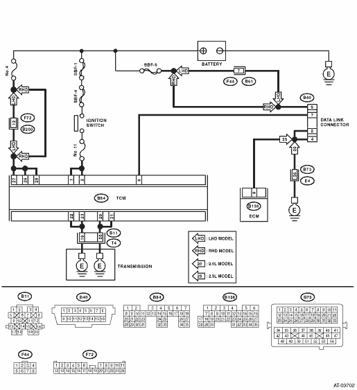
WIRING DIAGRAM:
1.CHECK BATTERY TERMINAL.
Turn the ignition switch to OFF.
|
Is there poor contact at the battery terminal?
|
Repair or tighten the battery terminal.
|
|
2.CHECK POWER SUPPLY OF TCM.
1) Disconnect the connector from TCM.
2) Turn the ignition switch to ON.
3) Measure the voltage between TCM connector and chassis ground.
Connector & terminal
(B54) No. 25 (+) — Chassis ground (−):
(B54) No. 26 (+) — Chassis ground (−):
(B54) No. 27 (+) — Chassis ground (−):
|
Is the voltage 10 — 13 V?
|
|
|
3.CHECK FUSE (NO. 4).
1) Turn the ignition switch to OFF.
2) Remove the fuse (No. 4).
|
Is the fuse (No. 4) blown out?
|
Replace the fuse (No. 4). If the replaced fuse (No. 4) has blown out easily, repair the short circuit of harness between fuse (No. 4) and TCM.
|
Repair the open circuit of harness between fuse (No. 4) and TCM, or fuse (No. 4) and battery, and poor contact of the connector.
|
4.CHECK IGNITION POWER SUPPLY CIRCUIT.
1) Turn the ignition switch to ON. (engine OFF)
2) Measure the ignition power supply voltage between TCM connector and chassis ground.
Connector & terminal
(B54) No. 1 (+) — Chassis ground (−):
(B54) No. 2 (+) — Chassis ground (−):
|
Is the voltage 10 — 13 V?
|
|
|
5.CHECK FUSE (NO. 11).
Remove the fuse (No. 11).
|
Is the fuse (No. 11) blown out?
|
Replace the fuse (No. 11). If the replaced fuse (No. 11) has blown out easily, repair the short circuit of harness between fuse (No. 11) and TCM.
|
Repair the open circuit of harness between fuse (No. 11) and TCM, or fuse (No. 11) and battery, and poor contact of the connector.
|
6.CHECK HARNESS CONNECTOR BETWEEN TCM AND TRANSMISSION.
1) Turn the ignition switch to OFF.
2) Disconnect the connectors from TCM and transmission.
3) Measure the resistance of harness between TCM and transmission connector.
Connector & terminal
(B54) No. 20 — (B11) No. 19:
(B54) No. 21 — (B11) No. 19:
(B54) No. 22 — (B11) No. 20:
(B54) No. 23 — (B11) No. 20:
|
Is the resistance less than 1 Ω?
|
|
Repair the open circuit of harness between TCM and transmission harness connector, and poor contact of connector.
|
7.CHECK HARNESS CONNECTOR BETWEEN TRANSMISSION AND TRANSMISSION GROUND.
Measure the resistance of the harness between transmission and transmission ground.
Connector & terminal
(T4) No. 19 — Transmission ground:
(T4) No. 20 — Transmission ground:
|
Is the resistance less than 1 Ω?
|
|
Repair the open circuit of the harness between transmission and transmission ground.
|
8.CHECK POOR CONTACT OF CONNECTORS.
|
Is there poor contact in TCM power supply, ground and data link connector?
|
|
Replace the TCM.
|