1.CHECK POWER SWITCH OPERATION.
|
When the power switch is turned to OFF, does the light illuminate?
|
|
|
2.CHECK POWER SWITCH OPERATION.
|
When the power switch is turned to ON, does the light illuminate?
|
Go to step CHECK HOLD SWITCH. 
|
|
3.CHECK POWER INDICATOR LIGHT.
1) Turn the ignition switch to OFF.
2) Remove the combination meter.
3) Remove the power indicator light bulb from combination meter.
|
Is the power indicator light bulb OK?
|
|
Replace the power indicator light bulb.
|
4.CHECK POWER SWITCH GROUND CIRCUIT.
1) Turn the ignition switch to OFF.
2) Disconnect the connector from power switch.
3) Measure the resistance of harness connector between power switch and chassis ground.
Connector & terminal
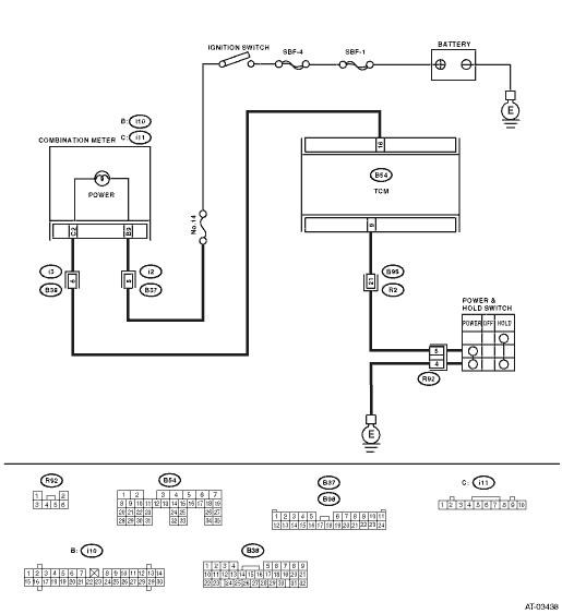
LHD model
(R92) No. 4 — Chassis ground:
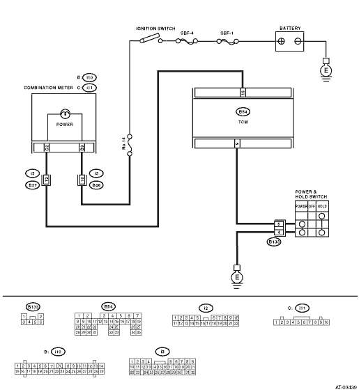
RHD model
(B133) No. 4 — Chassis ground:
|
Is the resistance less than 1 Ω?
|
|
Repair the open circuit of harness between power switch and chassis ground.
|
5.CHECK POWER SWITCH.
1) Turn the power switch to ON.
2) Measure the resistance between power switch terminals.
|
Is the resistance less than 1 Ω?
|
|
Replace the power switch.
|
6.CHECK POWER SWITCH.
1) Turn the power switch to OFF.
2) Measure the resistance between power switch terminals.
|
Is the resistance 1 MΩ or more?
|
|
Replace the power switch.
|
7.CHECK HARNESS CONNECTOR BETWEEN TCM AND POWER SWITCH.
Measure the resistance of harness connector between TCM and power switch.
Connector & terminal
LHD model
(B54) No. 9 — (R92) No. 5:
RHD model
(B54) No. 9 — (B133) No. 5:
|
Is the resistance less than 1 Ω?
|
|
Repair the open circuit of harness between TCM and power switch connector.
|
8.CHECK HARNESS CONNECTOR BETWEEN TCM AND POWER SWITCH.
Measure the resistance of the harness connector between TCM connector and chassis ground.
Connector & terminal
(B54) No. 9 — Chassis ground:
|
Is the resistance 1 MΩ or more?
|
|
Repair the short circuit of harness between TCM and power switch connector.
|
9.CHECK INPUT SIGNAL FOR TCM.
1) Connect the connector to TCM and power switch.
2) Turn the ignition switch to ON. (engine OFF)
3) Measure the signal voltage for TCM while the power switch is OFF.
Connector & terminal
(B54) No. 9 (+) — Chassis ground (−):
|
Is the voltage 10 V or more?
|
|
Replace the TCM.
|
10.CHECK INPUT SIGNAL FOR TCM.
Measure the signal voltage for TCM while the power switch is ON.
Connector & terminal
(B54) No. 9 (+) — Chassis ground (−):
|
Is the voltage less than 1 V?
|
|
Replace the TCM.
|
|
|
|
|
A temporary poor contact of the power switch circuit connector or harness may be the cause.
|