DTC DETECTING CONDITION:
Detected when two consecutive driving cycles with fault occur.
CAUTION:
After repairing or replacing the defective part, perform the Clear Memory Mode  and Inspection Mode .
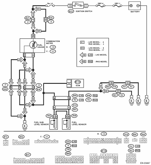
WIRING DIAGRAM:

| STEP | CHECK | YES | NO |
|
Does the speedometer and tachometer operate normally? |
|
Repair or replace the combination meter. |
|
|
Is the voltage less than 0.12 V? |
|
|
|
|
Does the voltage change when shaking the ECM harness and connector? |
Repair the poor contact of ECM connector. |
Even if the malfunction indicator light illuminates, the circuit has returned to a normal condition at this time. Temporary poor contact of connector may be the cause. NOTE: In this case, repair the following item: • Poor contact in combination meter connector • Poor contact in ECM connector • Poor contact of coupling connector |
|
|
1) Turn the ignition switch to OFF. 2) Separate fuel tank cord connector (R57) and rear wiring harness connector (R15). 3) Turn the ignition switch to ON. 4) Measure the voltage of harness between ECM connector and chassis ground. Connector & terminal (B135) No. 10 (+) — Chassis ground (−): |
Is the voltage 0.12 V or more? |
|
|
|
Is the resistance 1 MΩ or more? |
|
Repair the ground short circuit of harness between ECM and combination meter connector. |
|
|
Is the resistance less than 10 Ω? |
Repair or replace the combination meter. |
Repair the open circuit between ECM and combination meter connector. NOTE: In this case, repair the following item: Poor contact of coupling connector |
|
|
Is the resistance 1 MΩ or more? |
|
Repair the ground short circuit of fuel tank cord. |
|
|
Is the resistance 1 MΩ or more? |
|
Repair the ground short circuit of fuel tank cord. |
|
|
Is the resistance between 0.5 — 2.5 Ω? |
|
Replace the fuel level sensor. |
|
|
Is the resistance between 0.5 — 2.5 Ω? |
Repair the poor contact of harness between ECM and combination meter connector. |
Replace the fuel sub level sensor. |