1.CHECK OUTPUT SIGNAL OF ECM.
1) Turn the ignition switch to OFF.
2) Connect the test mode connector.
3) Turn the ignition switch to ON.
4) Check the voltage between ECM terminal and chassis ground during the radiator fan relay operation.
NOTE:
The radiator fan relay can be operated using the Subaru Select Monitor. Regarding the procedures, refer to “Compulsory Valve Operation Check Mode”. 
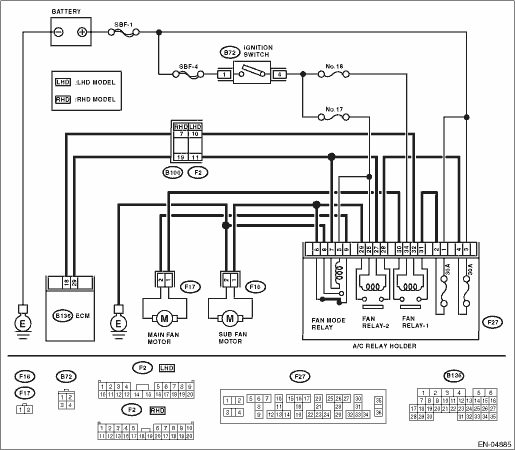
Connector & terminal
(B136) No. 29 (+) — Chassis ground (−):
(B136) No. 18 (+) — Chassis ground (−):
|
Does the voltage change between 0 — 10 V?
|
Repair the poor contact of ECM connector.
|
|
2.CHECK GROUND SHORT CIRCUIT OF RADIATOR FAN RELAY CONTROL.
1) Turn the ignition switch to OFF.
2) Disconnect the connectors from the ECM.
3) Measure the resistance of harness between ECM connector and chassis ground.
Connector & terminal
(B136) No. 29 — Chassis ground:
(B136) No. 18 — Chassis ground:
|
Is the resistance 1 MΩ or more?
|
|
Repair the ground short circuit of the radiator fan relay control.
|
3.CHECK POWER SUPPLY TO RELAY.
1) Remove the fan relay 1 and fan relay 2 form A/C relay holder.
2) Turn the ignition switch to ON.
3) Measure the voltage between fuse & relay box (F/B) connector and chassis ground.
Connector & terminal
(F27) No. 27 (+) — Chassis ground (−):
(F27) No. 32 (+) — Chassis ground (−):
|
Is the voltage 10 V or more?
|
|
Repair open circuit of the harness between ignition switch and fuse & relay box (F/B) connector.
|
4.CHECK FAN RELAY.
1) Turn the ignition switch to OFF.
2) Measure the resistance between fan relay terminals.
Terminals
No. 32 — No. 34: (fan relay 1)
No. 25 — No. 27: (fan relay 2)
|
Is the resistance between 87 — 107 Ω?
|
|
Replace the fan relay.
|
5.CHECK OPEN CIRCUIT OF FAN RELAY CONTROL.
Measure the resistance of harness between ECM and fan relay connector.
Connector & terminal
(B136) No. 29 — (F27) No. 27:
(B136) No. 18 — (F27) No. 32:
|
Is the resistance less than 1 Ω?
|
Temporary poor contact occurs.
|
Repair the harness and connector.
NOTE:
In this case, repair the following item:
• Open circuit of harness between ECM and fan relay connector
• Poor contact of coupling connector
|