1.CHECK SENSOR OUTPUT.
1) Turn the ignition switch to ON.
2) Measure the voltage between ECM connector terminals.
Connector & terminal
(B134) No. 18 (+) — (B134) No. 29 (−):
3) Check the voltage change while shaking the ECM harness and connector, engine harness connector, and electronic control throttle connector harness.
|
Is the voltage 0.4 V or more?
|
|
|
2.CHECK SENSOR OUTPUT.
1) Measure the voltage between ECM connector terminals.
Connector & terminal
(B134) No. 28 (+) — (B134) No. 29 (−):
2) Check the voltage change while shaking the ECM harness and connector, engine harness connector, and electronic control throttle connector harness.
|
Is the voltage 0.8 V or more?
|
|
|
3.CHECK POOR CONTACT.
Check poor contact in connector between ECM and electronic throttle.
|
|
|
|
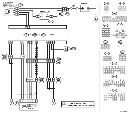
4.CHECK HARNESS BETWEEN ECM AND ELECTRONIC THROTTLE.
1) Turn the ignition switch to OFF.
2) Disconnect the connectors from the ECM.
3) Disconnect the connectors from electronic throttle.
4) Measure the resistance between ECM connector and electronic throttle connector.
Connector & terminal
(B134) No. 19 — (E57) No. 5:
|
Is the resistance less than 1 Ω?
|
|
Repair the open circuit of harness connector.
|
5.CHECK HARNESS BETWEEN ECM AND ELECTRONIC THROTTLE.
Measure the resistance between ECM connector and chassis ground.
Connector & terminal
(B134) No. 19 — Chassis ground:
(B134) No. 18 — Chassis ground:
(B134) No. 28 — Chassis ground:
|
Is the resistance 1 MΩ or more?
|
|
Repair the ground short circuit of harness.
|
6.CHECK SENSOR POWER SUPPLY.
1) Connect the ECM connector.
2) Turn the ignition switch to ON.
3) Measure the voltage between electronic throttle connector and engine ground.
Connector & terminal
(E57) No. 5 (+) — Engine ground (−):
4) Check the voltage change by shaking the harness and connector of ECM and engine harness connector while monitoring the value with voltage meter.
|
Is the voltage 4.5 — 5.5 V?
|
|
Repair the poor contact of ECM connector. Replace the ECM if defective. 
|
7.CHECK SHORT CIRCUIT IN ECM.
1) Turn the ignition switch to OFF.
2) Measure the resistance between electronic throttle connector and engine ground.
Connector & terminal
(E57) No. 4 — Engine ground:
(E57) No. 6 — Engine ground:
|
Is the resistance 10 Ω or more?
|
|
Repair the poor contact of ECM connector. Replace the ECM if defective.
|
8.CHECK SENSOR OUTPUT.
1) Connect all connectors.
2) Turn the ignition switch to ON.
3) Read the data of main throttle sensor signal using Subaru Select Monitor.
4) Check the voltage change while shaking the ECM harness and connector, engine harness connector, and electronic control throttle connector harness.
|
Is the voltage less than 4.63 V?
|
|
|
9.CHECK SENSOR OUTPUT.
1) Read the data of sub throttle sensor signal using Subaru Select Monitor.
2) Check the voltage change while shaking the ECM harness and connector, engine harness connector, and electronic control throttle connector harness.
|
Is the voltage less than 4.73 V?
|
|
|
10.CHECK POOR CONTACT.
Check poor contact in connector between ECM and electronic throttle.
|
|
|
Temporary poor contact occurred, but it is normal at present.
|
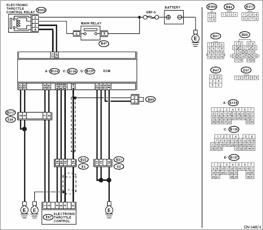
11.CHECK HARNESS BETWEEN ECM AND ELECTRONIC THROTTLE.
1) Turn the ignition switch to OFF.
2) Disconnect the connectors from the ECM.
3) Disconnect the connectors from electronic throttle.
4) Measure the resistance between ECM connector and electronic throttle connector.
Connector & terminal
(B134) No. 18 — (E57) No. 6:
(B134) No. 28 — (E57) No. 4:
(B134) No. 29 — (E57) No. 3:
|
Is the resistance less than 1 Ω?
|
|
Repair the open circuit of harness connector.
|
12.CHECK HARNESS BETWEEN ECM AND ELECTRONIC THROTTLE.
1) Connect the ECM connector.
2) Measure the resistance between electronic throttle connector and engine ground.
Connector & terminal
(E57) No. 3 — Engine ground:
|
Is the resistance less than 5 Ω?
|
|
Repair the poor contact of ECM connector. Replace the ECM if defective.
|
13.CHECK HARNESS BETWEEN ECM AND ELECTRONIC THROTTLE.
1) Connect the ECM connector.
2) Turn the ignition switch to ON.
3) Measure the voltage between electronic throttle connector and engine ground.
Connector & terminal
(E57) No. 5 (+) — Engine ground (−):
4) Check the voltage change by shaking the harness and connector of ECM and engine harness connector while monitoring the value with voltage meter.
|
Is the voltage less than 10 V?
|
|
Repair the short to power supply in harness between ECM connector and electronic throttle connector.
|
14.CHECK HARNESS BETWEEN ECM AND ELECTRONIC THROTTLE.
1) Measure the voltage between electronic throttle connector and engine ground.
Connector & terminal
(E57) No. 4 (+) — Engine ground (−):
(E57) No. 6 (+) — Engine ground (−):
2) Check the voltage change by shaking the harness and connector of ECM and engine harness connector while monitoring the value with voltage meter.
|
Is the voltage less than 10 V?
|
|
Repair the short circuit of harness between ECM connector and electronic throttle connector.
|
15.CHECK HARNESS BETWEEN ECM AND ELECTRONIC THROTTLE.
1) Turn the ignition switch to OFF.
2) Disconnect the ECM connector.
3) Measure the resistance between ECM connectors.
Connector & terminal
(B134) No. 18 — (B134) No. 29:
(B134) No. 28 — (B134) No. 29:
|
Is the resistance 1 MΩ or more?
|
|
Repair the short circuit to sensor power supply.
|
16.CHECK ELECTRONIC THROTTLE HARNESS.
1) Disconnect the connectors from the ECM.
2) Disconnect the connectors from electronic throttle.
3) Measure the resistance between electronic throttle connector terminals.
Connector & terminal
(E57) No. 6 — (E57) No. 4:
|
Is the resistance 1 MΩ or more?
|
Repair the poor contact of ECM connector. Replace the ECM if defective.
|
Repair the short circuit of harness.
|