1. HOW TO USE SUBARU SELECT MONITOR
1. Prepare the Subaru Select Monitor kit. 
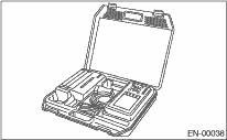
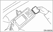
2. Connect the diagnosis cable to the Subaru Select Monitor.
3. Insert the cartridge to the Subaru Select Monitor.
4. Connect the Subaru Select Monitor to the data link connector.
(1) Data link connector is located in the lower portion of instrument panel (on the driver’s side).
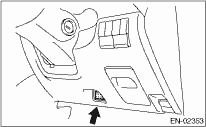
(2) Connect the diagnosis cable to the data link connector.
CAUTION:
Do not connect any scan tools except the Subaru Select Monitor or general scan tool.
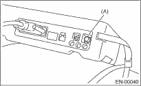
5. Turn the ignition switch to ON (engine OFF) and Subaru Select Monitor switch to ON.
|
(A) |
Power switch |
6. Using the Subaru Select Monitor, call up DTC and data, then record them.
2. READ DIAGNOSTIC TROUBLE CODE (DTC) FOR ENGINE (NORMAL MODE)
Refer to “Read Diagnostic Trouble Code” for information about how to indicate DTC.
3. READ DIAGNOSTIC TROUBLE CODE (DTC) FOR ENGINE (OBD MODE)
Refer to “Read Diagnostic Trouble Code” for information about how to indicate DTC.
4. READ CURRENT DATA FOR ENGINE (NORMAL MODE)
1. On the «Main Menu» display screen, select {Each System Check} and press the [YES] key.
2. On the «System Selection Menu» display screen, select {Engine Control System} and press the [YES] key.
3. Press the [YES] key after the information of engine type has been displayed.
4. On the «Engine Diagnosis» display screen, select the {Current Data Display/Save}, and then press the [YES] key.
5. On the «Display Menu» screen, select the {Data Display} and press the [YES] key.
6. Using the scroll key, scroll the display screen up or down until the desired data is shown.
• A list of the support data is shown in the following table.
|
Contents |
Display |
Unit of measure |
Note (at idling) |
|
Engine load |
Engine Load |
% |
1 — 3% |
|
Engine coolant temperature signal |
Coolant Temp. |
°C or °F |
≥ 75°C or 167°F |
|
A/F correction 1 |
A/F Correction 1 |
% |
−10 — +10% |
|
A/F learning 1 |
A/F Learning 1 |
% |
−15 — +15% |
|
Intake manifold absolute pressure |
Mani. Absolute Pressure |
mmHg, kPa, inHg or psig |
200 — 300 mmHg, 26.7 — 40 kPa, 7.8 — 11.8 inHg or 3.8 — 5.8 psig |
|
Engine speed signal |
Engine Speed |
rpm |
600 — 800 rpm (Agree with the tachometer indication) |
|
Meter vehicle speed signal |
Vehicle Speed |
km/h or MPH |
0 km/h or 0 MPH (at parking) |
|
Ignition timing signal |
Ignition Timing |
deg |
10 — 15 deg |
|
Intake air temperature signal |
Intake Air Temp. |
°C or °F |
20 — 50°C or 68 — 122°F |
|
Intake air amount |
Mass Air Flow |
g/s or lb/m |
2 — 7 g/s or 0.3 — 0.9 lb/m |
|
Throttle opening angle signal |
Throttle Opening Angle |
% |
1 — 5% |
|
Rear oxygen sensor voltage |
Rear O2 Sensor |
V |
0.01 — 0.85 V |
|
Battery voltage |
Battery Voltage |
V |
12 — 14 V |
|
Mass air flow voltage |
Air Flow Sensor Voltage |
V |
0.6 — 1.6 V |
|
Injection 1 pulse width |
Fuel Injection #1 Pulse |
ms |
2 — 4 ms |
|
Knock sensor correction |
Knocking Correction |
deg |
0.0 deg |
|
Atmospheric absolute pressure signal |
Atmosphere Pressure |
mmHg, kPa, inHg or psig |
(atmosphere pressure) |
|
Intake manifold relative pressure |
Intake manifold relative pressure |
mmHg, kPa, inHg or psig |
(Air intake absolute pressure − atmosphere pressure) |
|
Learned ignition timing |
Ignition learning value |
° |
−2 — 2° |
|
Acceleration opening angle signal |
Accel. Opening Angle |
% |
0.0% |
|
Rear oxygen sensor heater current |
Rear oxygen sensor heater current value |
A |
0.9 — 1.1 A |
|
Fuel level signal |
Fuel Level |
V |
0 — 5 V |
|
Purge control solenoid duty ratio |
CPC Duty |
% |
0 — 3% |
|
EGR steps |
No. of EGR Steps |
STEP |
0 |
|
Generator duty ratio |
ALT Duty |
% |
0 — 100% |
|
AVCS advance angle amount RH |
VVT advance angle amount R |
deg |
0 deg |
|
AVCS advance angle amount LH |
VVT advance angle amount L |
deg |
0 deg |
|
Oil flow control solenoid valve duty RH (AVCS) |
OCV duty R |
% |
20 — 30% |
|
Oil flow control solenoid valve duty LH (AVCS) |
OCV duty L |
% |
20 — 30% |
|
Oil flow control solenoid valve current RH |
OCV current R |
mA |
100 — 200 mA |
|
Oil flow control solenoid valve current LH |
OCV current L |
mA |
100 — 200 mA |
|
A/F sensor resistance value 1 |
A/F Sensor #1 Resistance |
Ω |
23 — 27 Ω |
|
A/F sensor output lambda 1 |
A/F Sensor 1 |
— |
0.85 — 1.15 |
|
A/F correction 3 |
A/F Correction 3 |
% |
3.5 — 6.5% |
|
Front oxygen (A/F) sensor current |
A/F heater current value |
A |
5 — 10 A |
|
Main throttle position sensor fully closed point voltage |
Main throttle sensor fully closed voltage |
V |
0.3 — 0.9 V |
|
Throttle motor duty |
Throttle Motor Duty |
% |
5 — 15% |
|
Throttle power supply voltage |
Throttle Motor Voltage |
V |
(Battery voltage) |
|
Sub throttle sensor voltage |
Sub-throttle Sensor |
V |
0.54 V |
|
Main throttle sensor voltage |
Main-throttle Sensor |
V |
0.54 V |
|
Sub accelerator sensor voltage |
Sub-accelerator Sensor |
V |
0.66 V |
|
Main accelerator sensor voltage |
Main-accelerator Sensor |
V |
0.68 V |
|
Secondary air pipe pressure signal |
Secondary air pipe pressure |
mmHg, kPa, inHg or psig |
765 mmHg, 102 kPa, 30.1 inHg or 14.8 psig |
|
Secondary airflow signal |
Secondary airflow amount |
g/s or lb/m |
0.00 g/s or 0.00 lb/m |
|
Memory vehicle speed (AT model) |
Memorized Cruise Speed |
km/h or MPH |
0 km/h or 0 MPH |
|
Fuel level sensor resistance |
Fuel level resistance |
Ω |
0.0 Ω |
|
#1 cylinder roughness monitor |
Roughness Monitor #1 |
— |
0 |
|
#2 cylinder roughness monitor |
Roughness Monitor #2 |
— |
0 |
|
#3 cylinder roughness monitor |
Roughness Monitor #3 |
— |
0 |
|
#4 cylinder roughness monitor |
Roughness Monitor #4 |
— |
0 |
|
AT/MT identification terminal |
AT Vehicle ID Signal |
— |
ON/OFF |
|
Test mode terminal |
Test Mode Terminal |
— |
U-check |
|
Neutral position switch signal |
Neutral Position Switch |
— |
Neutral |
|
Soft idle switch signal |
Soft Idle SW |
— |
Idling |
|
Ignition switch signal |
Ignition Switch |
— |
ON input |
|
Power steering switch signal |
P/S Switch |
— |
OFF input (At OFF) |
|
Air conditioning switch signal |
A/C Switch |
— |
OFF input (At OFF) |
|
Steering wheel switch signal |
Steering Wheel SW |
— |
HIGH Input/LOW Input |
|
Starter switch signal |
Starter Switch |
— |
OFF input |
|
Rear oxygen monitor |
Rear O2 Rich Signal |
— |
Rich/Lean |
|
Knocking signal |
Knocking Signal |
— |
None |
|
Crankshaft position sensor signal |
Crankshaft Position Signal |
— |
Provided |
|
Camshaft position sensor signal |
Camshaft Position Signal |
— |
Provided |
|
Rear defogger switch signal |
Rear Defogger Switch |
— |
OFF input (At OFF) |
|
Blower fan switch signal |
Blower Fan Switch |
— |
OFF input (At OFF) |
|
Light switch signal |
Light Switch |
— |
OFF input (At OFF) |
|
Wiper switch signal |
Wiper Switch |
— |
OFF input (At OFF) |
|
A/C middle pressure switch signal |
A/C Mid Pressure Switch |
— |
OFF input (At OFF) |
|
Air conditioner compressor relay output signal |
A/C Compressor Signal |
— |
OFF output (At OFF) |
|
Radiator fan relay 1 signal |
Radiator Fan Relay #1 |
— |
OFF output (At OFF) |
|
Radiator fan relay 2 signal |
Radiator Fan Relay #2 |
— |
OFF output (At OFF) |
|
Fuel pump relay signal |
Fuel Pump Relay |
— |
ON output |
|
AT coordinate retard angle demand signal |
Retard Signal from AT |
— |
None |
|
AT coordinate fuel cut demand signal |
Fuel Cut Signal from AT |
— |
None |
|
AT coordinate permission signal |
Torque Control Permission Signal |
— |
ON/OFF |
|
Electronic throttle motor relay signal |
ETC Motor Relay |
— |
ON |
|
Clutch switch signal |
Clutch Switch |
— |
OFF input (At OFF) |
|
Stop light switch signal |
Stop Light Switch |
— |
OFF input (At OFF) |
|
SET/COAST switch signal |
SET/COAST Switch |
— |
OFF input (At OFF) |
|
RESUME/ACCEL switch signal |
RESUME/ACCEL Switch |
— |
OFF input (At OFF) |
|
Brake switch signal |
Brake Switch |
— |
OFF input (At OFF) |
|
Main switch signal |
Main Switch |
— |
OFF input (At OFF) |
|
Secondary air pump relay signal |
Secondary air pump relay |
— |
OFF (At OFF) |
|
Secondary Air Combination Valve Relay 1 signal |
Secondary air combination valve relay 1 |
— |
OFF (At OFF) |
|
Cruise control cancel switch signal (model with cruise control) |
CC Cancel SW |
— |
OFF |
NOTE:
For detailed operation procedure, refer to the “SUBARU SELECT MONITOR OPERATION MANUAL”.
5. READ CURRENT DATA FOR ENGINE (OBD MODE)
1. On the «Main Menu» display screen, select {Each System Check} and press the [YES] key.
2. On the «System Selection Menu» display screen, select {Engine Control System} and press the [YES] key.
3. Press the [YES] key after the information of engine type has been displayed.
4. On the «Engine Diagnosis» display screen, select {OBD System} and press the [YES] key.
5. On the «OBD Menu» screen, select {Current Data Display/Save}, and then press the [YES] key.
6. On the «Display Menu» screen, select the {Data Display} and press the [YES] key.
7. Using the scroll key, scroll the display screen up or down until the desired data is shown.
• A list of the support data is shown in the following table.
|
Remarks |
Display |
Unit of measure |
Note (at idling) |
|
Number of diagnosis code |
Number of DTC |
— |
— |
|
Condition of malfunction indicator light |
MI (MIL) |
— |
ON or OFF |
|
Monitoring test of misfire |
Misfire monitoring |
— |
Supp YES |
|
Monitoring test of misfire |
Misfire monitoring |
— |
Rdy YES/Rdy NO |
|
Monitoring test of fuel system |
Fuel system monitoring |
— |
Supp YES |
|
Monitoring test of fuel system |
Fuel system monitoring |
— |
Rdy YES/Rdy NO |
|
Monitoring test of comprehensive component |
Component monitoring |
— |
Supp YES |
|
Monitoring test of comprehensive component |
Component monitoring |
— |
Rdy YES/Rdy NO |
|
Test of catalyst |
Catalyst Diagnosis |
— |
Supp YES |
|
Test of catalyst |
Catalyst Diagnosis |
— |
Rdy YES/Rdy NO |
|
Test of heating-type catalyst |
Heated catalyst |
— |
Supp NO |
|
Test of heating-type catalyst |
Heated catalyst |
— |
Rdy N/A |
|
Test of evaporative emission purge control system |
Evaporative purge system |
— |
Supp NO |
|
Test of evaporative emission purge control system |
Evaporative purge system |
— |
Rdy N/A |
|
Test of secondary air system |
Secondary air system |
— |
Supp YES |
|
Test of secondary air system |
Secondary air system |
— |
Rdy YES/Rdy NO |
|
Test of air conditioning system |
A/C system refrigerant |
— |
Supp NO |
|
Test of air conditioning system |
A/C system refrigerant |
— |
Rdy N/A |
|
Test of oxygen sensor |
Oxygen sensor |
— |
Supp YES |
|
Test of oxygen sensor |
Oxygen sensor |
— |
Rdy YES/Rdy NO |
|
Test of oxygen sensor heater |
O2 Heater Diagnosis |
— |
Supp YES |
|
Test of oxygen sensor heater |
O2 Heater Diagnosis |
— |
Rdy YES/Rdy NO |
|
Test of EGR system |
EGR system |
— |
Supp YES |
|
Test of EGR system |
EGR system |
— |
Rdy YES/Rdy NO |
|
Air fuel ratio control system for bank 1 |
A/F Control #1 |
— |
CLOSE |
|
Engine load data |
Calculated load value |
% |
1 — 3% |
|
Engine coolant temperature signal |
Coolant Temp. |
°C or °F |
75°C or more, or 167°F or more |
|
Short term fuel trim by front oxygen (A/F) sensor |
A/F Correction Value #1 |
% |
−10 — +10% |
|
Long term fuel trim by front oxygen (A/F) sensor |
A/F Learning Value #1 |
% |
−15 — +15% |
|
Intake manifold absolute pressure signal |
Mani. Absolute Pressure |
mmHg, kPa, inHg or psig |
200 — 300 mmHg, 27 — 40 kPa, 7.9 — 11.8 inHg or 3.9 — 5.8 psig |
|
Engine speed signal |
Engine Speed |
rpm |
600 — 800 rpm |
|
Vehicle speed signal |
Vehicle Speed |
km/h or MPH |
0 km/h or 0 MPH |
|
#1 Cylinder ignition timing |
Ignition timing #1 |
° |
+10 — +20° |
|
Intake air temperature signal |
Intake Air Temp. |
°C or °F |
(ambient temperature) (50°C or up to 122°F) |
|
Intake air amount |
Mass Air Flow |
g/s or lb/m |
2 — 7 g/s or 0.3 — 0.9 lb/m |
|
Throttle position signal |
Throttle Opening Angle |
% |
1 — 5% |
|
Secondary air system |
Secondary air system |
— |
Stop |
|
Oxygen sensor #12 |
Oxygen sensor #12 |
V |
0.01 — 0.85 V |
|
Air fuel ratio correction by rear oxygen sensor |
A/F Correction #12 |
% |
3.5 — 6.5% |
|
On-board diagnostic system |
OBD System |
— |
EOBD |
|
Oxygen sensor #11 |
Oxygen sensor #11 |
— |
Support |
|
Rear oxygen sensor output signal |
Oxygen sensor #12 |
— |
Support |
|
Driving distance after the malfunction indicator light illuminates |
Lighted MI Lamp History |
km or miles |
0 km or 0 miles |
|
A/F lambda signal |
A/F sensor #11 |
— |
0.85 — 1.15 |
|
A/F sensor output signal |
A/F sensor #11 |
V |
2.3 — 3.0 V |
|
Target EGR |
Target EGR |
% |
— |
|
EGR status |
EGR Status |
% |
— |
|
Evaporative purge |
Evaporative Purge |
% |
— |
|
Fuel Level |
Fuel Level |
% |
— |
|
Number of warm-ups after DTC clear |
Number Of Warm-ups After DTC Clear |
— |
— |
|
Travel distance after DTC clear |
Travel Distance After DTC Clear |
km or MPH |
— |
|
Atmosphere pressure |
Atmosphere Pressure |
mmHg, kPa, inHg or psig |
— |
|
Monitoring test of misfire |
Misfire monitoring |
— |
Enable YES/NO |
|
Monitoring test of misfire |
Misfire monitoring |
— |
Comp YES/NO |
|
Monitoring test of fuel system |
Fuel system monitoring |
— |
Enable YES/NO |
|
Monitoring test of fuel system |
Fuel system monitoring |
— |
Comp YES/NO |
|
Monitoring test of comprehensive component |
Component monitoring |
— |
Enable YES/NO |
|
Monitoring test of comprehensive component |
Component monitoring |
— |
Comp YES/NO |
|
Test of catalyst |
Catalyst Diagnosis |
— |
Enable YES/NO |
|
Test of catalyst |
Catalyst Diagnosis |
— |
Comp YES/NO |
|
Test of heating-type catalyst |
Heated catalyst |
— |
Enable N/A |
|
Test of heating-type catalyst |
Heated catalyst |
— |
Comp N/A |
|
Test of evaporative emission purge control system |
Evaporative purge system |
— |
Enable N/A |
|
Test of evaporative emission purge control system |
Evaporative purge system |
— |
Comp N/A |
|
Test of secondary air system |
Secondary air system |
— |
Enable YES/NO |
|
Test of secondary air system |
Secondary air system |
— |
Comp YES/NO |
|
Test of air conditioning system |
A/C system refrigerant |
— |
Enable N/A |
|
Test of air conditioning system |
A/C system refrigerant |
— |
Comp N/A |
|
Test of oxygen sensor |
Oxygen sensor |
— |
Enable YES/NO |
|
Test of oxygen sensor |
Oxygen sensor |
— |
Comp YES/NO |
|
Test of oxygen sensor heater |
O2 Heater Diagnosis |
— |
Enable YES/NO |
|
Test of oxygen sensor heater |
O2 Heater Diagnosis |
— |
Comp YES/NO |
|
Test of EGR system |
EGR system |
— |
Enable YES/NO |
|
Test of EGR system |
EGR system |
— |
Comp YES/NO |
|
ECM power voltage |
ECM power voltage |
V |
— |
|
Absolute load |
Absolute load |
% |
— |
|
A/F target lambda |
A/F Target Lambda |
— |
— |
|
Relative throttle position |
Relative throttle position |
% |
— |
|
Ambient temperature |
Ambient temperature |
°C or °F |
— |
|
Absolute throttle opening angle 2 |
Absolute throttle opening angle 2 |
% |
— |
|
Absolute accelerator opening angle 1 |
Absolute accelerator opening angle 1 |
% |
— |
|
Absolute accelerator opening angle 2 |
Absolute accelerator opening angle 2 |
% |
— |
|
Target throttle opening angle |
Target throttle opening angle |
% |
— |
|
Engine operating time during MIL illumination |
Engine operating time during MIL illumination |
min |
— |
|
Elapsed time after DTC clear |
Elapsed time after DTC clear |
min |
— |
|
Fuel used |
Fuel used |
— |
GAS |
|
Relative throttle opening angle |
Relative throttle opening angle |
% |
— |
NOTE:
For detailed operation procedure, refer to the “SUBARU SELECT MONITOR OPERATION MANUAL”.
6. READ FREEZE FRAME DATA FOR ENGINE (OBD MODE)
1. On the «Main Menu» display screen, select {Each System Check} and press the [YES] key.
2. On the «System Selection Menu» display screen, select {Engine Control System} and press the [YES] key.
3. Press the [YES] key after the information of engine type has been displayed.
4. On the «Engine Diagnosis» display screen, select {OBD System} and press the [YES] key.
5. On the »OBD Menu» display screen, select the {Freeze Frame Data} and press the [YES] key.
• A list of the support data is shown in the following table.
|
Description |
Display |
Unit of measure |
Note |
|
DTCs of freeze frame data |
Freeze code |
Diagnostic trouble code (DTC) |
— |
|
Air fuel ratio control system for bank 1 |
Fuel system for Bank 1 |
Closed Loop or Open Loop |
— |
|
Oxygen sensor output voltage |
Oxygen sensor #12 |
V |
— |
|
Short term fuel trim by oxygen sensor |
Short term fuel trim B1 |
% |
— |
|
Engine load data |
Engine Load |
% |
— |
|
Engine coolant temperature signal |
Coolant Temp. |
°C or °F |
— |
|
Short term fuel trim by front oxygen (A/F) sensor |
Short term fuel trim B1 |
% |
— |
|
Long term fuel trim by front oxygen (A/F) sensor |
Long term fuel trim B1 |
% |
— |
|
Intake manifold absolute pressure signal |
Mani. Absolute Pressure |
mmHg, kPa, inHg or psi |
— |
|
Engine speed signal |
Engine Speed |
rpm |
— |
|
Vehicle speed signal |
Vehicle Speed |
km/h or MPH |
— |
|
Ignition timing advance for #1 cylinder |
Ignition timing advance #1 |
° |
— |
|
Intake air temperature signal |
Intake Air Temp. |
°C or °F |
— |
|
Intake air amount |
Mass Air Flow |
g/s or lb/m |
— |
|
Throttle position signal |
Throttle Opening Angle |
% |
— |
|
Secondary air system |
Secondary air system |
— |
— |
|
Oxygen sensor #11 |
Oxygen sensor #11 |
— |
Support |
|
Oxygen sensor #12 |
Oxygen sensor #12 |
— |
Support |
|
Elapsed time after starting engine |
Elapsed Time After starting Engine |
sec |
— |
|
Target EGR |
Target EGR |
% |
— |
|
EGR status |
EGR Status |
% |
— |
|
Evaporative purge |
Evaporative Purge |
% |
— |
|
Fuel Level |
Fuel Level |
% |
— |
|
Atmosphere pressure |
Atmosphere Pressure |
mmHg, kPa, inHg or psig |
— |
|
ECM power supply voltage |
ECM power supply voltage |
V |
— |
|
Absolute load |
Absolute load |
% |
— |
|
A/F target lambda |
A/F Target Lambda |
— |
— |
|
Relative throttle opening angle |
Relative throttle opening angle |
% |
— |
|
Ambient temperature |
Ambient temperature |
°C or °F |
— |
|
Absolute throttle opening angle 2 |
Absolute throttle opening angle 2 |
% |
— |
|
Absolute accelerator opening angle 1 |
Absolute accelerator opening angle 1 |
% |
— |
|
Absolute accelerator opening angle 2 |
Absolute accelerator opening angle 2 |
% |
— |
|
Target throttle opening angle |
Target Throttle Opening Angle |
% |
— |
NOTE:
For detailed operation procedure, refer to the “SUBARU SELECT MONITOR OPERATION MANUAL”.
7. LED OPERATION MODE FOR ENGINE
1. On the «Main Menu» display screen, select {Each System Check} and press the [YES] key.
2. On the «System Selection Menu» display screen, select {Engine Control System} and press the [YES] key.
3. Press the [YES] key after the information of engine type has been displayed.
4. On the «Engine Diagnosis» display screen, select the {Current Data Display/Save}, and then press the [YES] key.
5. On the «Data Display» screen, select {Data LED Display} and press the [YES] key.
6. Using the scroll key, scroll the display screen up or down until the desired data is shown.
• A list of the support data is shown in the following table.
|
Remarks |
Display |
Message |
When LED “ON” is required |
|
AT/MT identification signal |
AT Vehicle ID Signal |
ON or OFF |
Illuminate (AT model) |
|
Test mode signal |
Test Mode Terminal |
U check or D check |
D check |
|
Neutral position switch signal |
Neutral Position Switch |
ON or OFF |
When neutral position signal is input. |
|
Idle switch signal |
Soft Idle SW |
Idle or Other than Idle |
When idle switch signal is input. |
|
Ignition switch signal |
Ignition Switch |
ON or OFF |
When ignition switch is turned ON. |
|
Power steering switch signal |
P/S Switch |
ON or OFF |
When power steering switch is entered. |
|
Air conditioning switch signal |
A/C Switch |
ON or OFF |
When air conditioning switch is input. |
|
Steering wheel switch signal |
Steering Wheel SW |
LOW or HIGH |
When steering wheel switch LOW signal is input. |
|
Starter switch signal |
Starter Switch |
ON or OFF |
When starter switch is input. |
|
Rear oxygen sensor rich signal |
Rear O2 Rich Signal |
Rich or Lean |
When rear oxygen sensor mixture ratio is rich. |
|
Knocking signal |
Knocking Signal |
Provided or None |
When knocking signal is input. |
|
Crankshaft position sensor signal |
Crankshaft Position Signal |
Provided or None |
When crankshaft position sensor signal is input. |
|
Camshaft position sensor signal |
Camshaft Position Signal |
Provided or None |
When camshaft position sensor signal is input. |
|
Rear defogger switch signal |
Rear Defogger Switch |
ON or OFF |
When rear defogger switch is turned to ON. |
|
Blower fan switch signal |
Blower Fan Switch |
ON or OFF |
When blower fan switch is turned to ON. |
|
Light switch signal |
Light Switch |
ON or OFF |
When light switch is turned ON. |
|
Wiper switch signal |
Wiper Switch |
ON or OFF |
When windshield wiper switch is turned to ON. |
|
A/C middle pressure switch signal |
A/C Mid Pressure Switch |
ON or OFF |
When A/C middle pressure switch is turned to ON. |
|
Air conditioning relay signal |
A/C Compressor Signal |
ON or OFF |
When air conditioning relay is in function. |
|
Radiator fan relay 1 signal |
Radiator Fan Relay #1 |
ON or OFF |
When radiator fan relay 1 is in function. |
|
Radiator fan relay 2 signal |
Radiator Fan Relay #2 |
ON or OFF |
When radiator fan relay 2 is in function. |
|
Fuel pump relay signal |
Fuel Pump Relay |
ON output/OFF output |
ON output |
|
AT retard angle demand signal |
Retard Signal |
Provided or None |
When AT retard angle demand signal is input. |
|
AT fuel cut signal |
Fuel Cut |
Provided or None |
When AT fuel cut signal is input. |
|
AT coordinate permission signal |
Torque Control Permission Signal |
Permitted or Prohibited |
When AT coordinate permission signal is input. |
|
Electronic throttle motor relay signal |
ETC Motor Relay |
ON or OFF |
When electronic throttle motor relay is in function. |
|
Clutch switch signal |
Clutch Switch |
ON or OFF |
When clutch switch is turned to ON. |
|
Stop light switch signal |
Stop Light Switch |
ON or OFF |
When stop light switch is turned ON. |
|
SET/COAST switch signal |
SET/COAST Switch |
ON or OFF |
When SET/COAST switch is turned to ON. |
|
RES/ACC switch signal |
RESUME/ACCEL Switch |
ON or OFF |
When RES/ACC switch is turned to ON. |
|
Brake switch signal |
Brake Switch |
ON or OFF |
When brake switch is turned to ON. |
|
Main switch signal |
Main Switch |
ON or OFF |
When main switch is turned to ON. |
|
Secondary air pump relay signal |
Air pump relay |
ON or OFF |
Secondary air pump relay function |
|
Secondary Air Combination Valve 1 signal |
Combination valve 1 |
ON or OFF |
Secondary air combination valve 2 is ON |
|
Cancel switch signal |
Cancel Switch |
ON or OFF |
When cancel switch is turned to ON. |
NOTE:
For detailed operation procedure, refer to the “SUBARU SELECT MONITOR OPERATION MANUAL”.