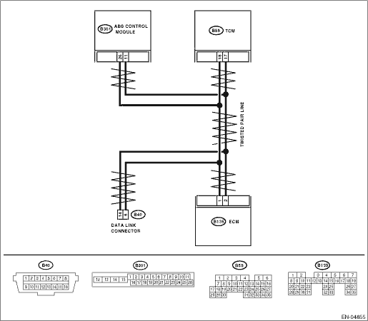
1.CHECK HARNESS BETWEEN ECM AND TCM.
1) Turn the ignition switch to OFF.
2) Disconnect the connector from ECM and TCM.
3) Measure the resistance between ECM and TCM connectors.
Connector & terminal
(B135) No. 1 — (B55) No. 18:
(B135) No. 2 — (B55) No. 17:
|
Is the resistance 1 Ω or less?
|
|
Repair the harness and connector.
NOTE:
In this case, repair the following item:
• Open circuit of harness between ECM and TCM connector
• Poor contact of joint connector
|
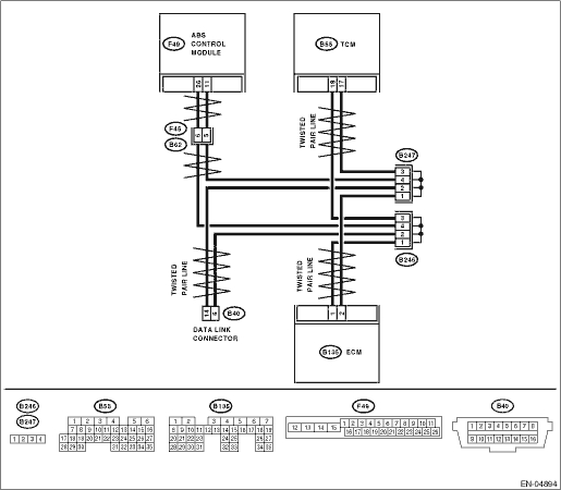
2.CHECK HARNESS BETWEEN ECM AND ABSCM&H/U.
1) Disconnect the ABSCM&H/U connectors.
2) Measure the resistance between the ECM and ABSCM&H/U connector.
Connector & terminal
LHD model
(B135) No. 1 — (B301) No. 26:
(B135) No. 2 — (B301) No. 11:
RHD model
(B135) No. 1 — (F49) No. 26:
(B135) No. 2 — (F49) No. 11:
|
Is the resistance 1 Ω or less?
|
|
Repair the harness and connector.
NOTE:
In this case, repair the following item:
• Open circuit of harness between ECM and ABSCM&H/U connector
• Poor contact of joint connector
|
3.CHECK HARNESS BETWEEN ECM AND DATA LINK CONNECTOR.
Measure the resistance between ECM and data link connector.
Connector & terminal
(B135) No. 1 — (B40) No. 11:
(B135) No. 2 — (B40) No. 3:
|
Is the resistance 1 Ω or less?
|
|
Repair the harness and connector.
NOTE:
In this case, repair the following item:
• Open circuit of harness between ECM and data link connector
• Poor contact of joint connector
|
4.CHECK HARNESS BETWEEN ECM, TCM AND ABSCM&H/U.
Measure the resistance between ECM connector and chassis ground.
Connector & terminal
(B135) No. 1 — Chassis ground:
(B135) No. 2 — Chassis ground:
|
Is the resistance 1 MΩ or more?
|
|
Repair the ground short circuit of harness between ECM, TCM and ABSCM&H/U.
|
5.CHECK HARNESS BETWEEN ECM, TCM AND ABSCM&H/U.
Check the resistance between ECM connectors.
Connector & terminal
(B135) No. 1 — (B135) No. 2:
|
Is the resistance 1 MΩ or more?
|
|
Repair the short circuit of harness between ECM, TCM and ABSCM&H/U.
|
6.CHECK THE STATUS OF THE AT SYSTEM.
Diagnose the AT using the Subaru Select Monitor.
|
|
|
|
7.CHECK THE STATUS OF THE ABS SYSTEM.
Diagnose the ABS using the Subaru Select Monitor.
|
|
|
Repair the poor contact of ECM connector. Replace the ECM if defective. 
|