ENGINE (DIAGNOSTICS)(H4DO) > Diagnostic Procedure with Diagnostic Trouble Code (DTC)

DTC P1521 BRAKE SWITCH CIRCUIT RANGE/PERFORMANCE PROBLEM (HIGH INPUT)

DTC DETECTING CONDITION:

Immediately at fault recognition

CAUTION:

After repairing or replacing the defective part, perform the Clear Memory Mode and Inspection Mode .
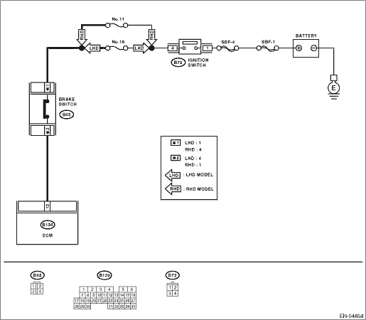
WIRING DIAGRAM:

STEPCHECKYESNO

1.CHECK INPUT SIGNAL OF ECM.

1) Turn the ignition switch to ON.

2) Measure the voltage between ECM and chassis ground.

Connector & terminal

(B136) No. 12 (+) — Chassis ground (−):

Is the voltage 10 V or more?

Repair the power supply short circuit between ECM and brake switch.

2.CHECK INPUT SIGNAL OF ECM.

1) Turn the ignition switch to ON.

2) Measure the voltage between ECM and chassis ground with the brake pedal depressed.

Connector & terminal

(B136) No. 12 (+) — Chassis ground (−):

Is the voltage 10 V or more?

Repair the ground short circuit between ECM and brake switch.

3.CHECK BRAKE SWITCH.

1) Turn the ignition switch to OFF.

2) Measure the resistance between brake switch connectors.

Terminals

(B65) No. 1 — (B65) No. 4:

Is the resistance less than 1 Ω?

Replace the brake switch.

4.CHECK BRAKE SWITCH.

Measure the resistance of the brake switch connectors with the brake pedal depressed.

Terminals

(B65) No. 1 — (B65) No. 4:

Is the resistance 1 MΩ or more?

Replace the brake switch.

Check poor contact of ECM connector.