1.CHECK BATTERY.
Check the battery voltage.
|
Is the voltage 12 V or more?
|
|
Charge or replace the battery. 
|
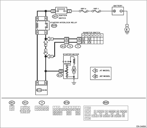
2.CHECK OPERATION OF STARTER MOTOR.
|
Does the starter motor operate?
|
|
|
|
|
Is DTC displayed?
|
Check the appropriate DTC using the List of Diagnostic Trouble Code (DTC).
|
Repair the poor contact of ECM connector.
|
4.CHECK INPUT SIGNAL FOR STARTER MOTOR.
1) Turn the ignition switch to OFF.
2) Disconnect the connector from starter motor.
3) Turn the ignition switch to START.
4) Measure the power supply voltage between starter motor connector terminal and engine ground.
Connector & terminal
(B14) No. 1 (+) — Engine ground (−):
NOTE:
• For AT model, place the select lever in “P” or “N” range.
• For MT model, depress the clutch pedal.
|
Is the voltage 10 V or more?
|
Check the starter motor.
|
|
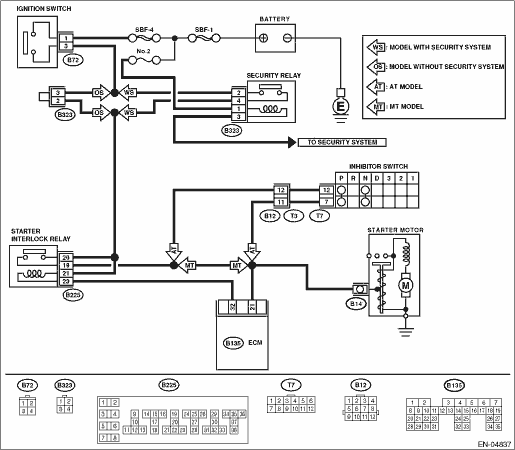
5.CHECK HARNESS BETWEEN BATTERY AND IGNITION SWITCH CONNECTOR.
1) Disconnect the connector from ignition switch.
2) Measure the power supply voltage between ignition switch connector and chassis ground.
Connector & terminal
(B72) No. 1 (+) — Chassis ground (−):
|
Is the voltage 10 V or more?
|
|
Repair the open circuit of harness between ignition switch and battery, and check fuse SBF No. 4 and SBF No. 1.
|
6.CHECK IGNITION SWITCH.
1) Disconnect the connector from ignition switch.
2) Measure the resistance between ignition switch terminals after turning the ignition switch to START position.
|
Is the resistance less than 5 Ω?
|
|
Replace the ignition switch.
|
7.CHECK TRANSMISSION TYPE.
Check the type of the transmission.
|
Is the transmission type AT?
|
|
|
8.CHECK INPUT VOLTAGE OF INHIBITOR SWITCH.
1) Turn the ignition switch to OFF.
2) Disconnect the connector from inhibitor switch.
3) Connect the connector to the ignition switch.
4) Measure the input voltage between inhibitor switch connector terminal and engine ground while turning the ignition switch to START.
Connector & terminal
(B12) No. 12 (+) — Engine ground (−):
|
Is the voltage 10 V or more?
|
|
Repair open or ground short circuit of harness between inhibitor switch and ignition switch.
NOTE:
Check security system (if equipped).
|
9.CHECK INHIBITOR SWITCH.
1) Place the select lever in “P” or “N” range.
2) Measure the resistance between inhibitor switch terminals.
|
Is the resistance less than 1 Ω?
|
|
Replace the inhibitor switch.
|
10.CHECK INPUT VOLTAGE OF STARTER INTERLOCK RELAY.
1) Turn the ignition switch to OFF.
2) Disconnect the connector from starter interlock relay.
3) Connect the connector to ignition switch.
4) Measure the input voltage between starter interlock relay connector and chassis ground after turning the ignition switch to START position.
Connector & terminal
LHD model
(B225) No. 26 (+) — Chassis ground (−):
(B225) No. 28 (+) — Chassis ground (−):
RHD model
(B225) No. 21 (+) — Chassis ground (−):
(B225) No. 20 (+) — Chassis ground (−):
|
Is the voltage 10 V or more?
|
|
Repair open or short circuit to ground in harness between starter interlock relay and ignition switch.
NOTE:
Check security system (if equipped).
|
11.CHECK STARTER INTERLOCK RELAY.
1) Connect the battery to the starter interlock relay terminals No. 26 and No. 24 (LHD model), or to No. 21 and No. 23 (RHD model).
2) Measure the resistance between starter interlock relay terminals.
Terminals
LHD model
No. 27 — No. 28:
RHD model
No. 19 — No. 20:
|
Is the resistance less than 1 Ω?
|
|
Replace the starter interlock relay.
|
12.CHECK INPUT VOLTAGE OF ECM.
1) Turn the ignition switch to OFF.
2) Connect the connector to starter interlock relay.
3) Disconnect the connectors from the ECM.
4) Measure the voltage between ECM and chassis ground.
Connector & terminal
(B135) No. 32 (+) — Chassis ground (−):
(B135) No. 21 (+) — Chassis ground (−):
|
Is the voltage 10 V or more?
|
Replace the ECM.
|
Repair the open or ground short circuit of harness between ECM and starter relay.
|