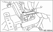
1. Install the front cushion rubbers.
Tightening torque:
35 N·m (3.6 kgf-m, 25.8 ft-lb)
2. Apply a small amount of grease to splines of mainshaft. (MT model)
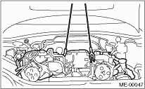
3. Position the engine in engine compartment and align it with transmission.
NOTE:
Be careful not to damage adjacent parts or body panels with crank pulley, oil level gauge, etc.
4. Tighten the bolts which hold upper side of transmission to engine.
Tightening torque:
50 N·m (5.1 kgf-m, 36.9 ft-lb)
5. Remove the lifting device and wire ropes.
6. Remove the garage jack.
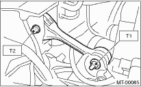
7. Install the pitching stopper.
Tightening torque:
T1: 50 N·m (5.1 kgf-m, 37 ft-lb)
T2: 58 N·m (5.9 kgf-m, 43 ft-lb)
8. Remove the ST from converter case. (AT model)
NOTE:
Be careful not to drop the ST into the converter case when removing the ST.
| ST 498277200 | STOPPER SET |
9. Install the starter. 
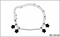
10. Install the torque converter clutch to drive plate. (AT model)
(1) Tighten the bolts which hold torque converter clutch to drive plate.
(2) Tighten other bolts while rotating the engine using a socket wrench.
NOTE:
Be careful not to drop bolts into the torque converter clutch housing.
Tightening torque:
25 N·m (2.5 kgf-m, 18.1 ft-lb)
(3) Fit the plug to service hole.
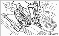
11. Install the power steering pump.
(1) Install the reservoir tank to the bracket.
(2) Install the power steering pump.
Tightening torque:
20.1 N·m (2.05 kgf-m, 14.8 ft-lb)
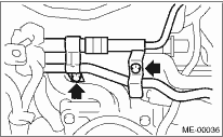
(3) Install the power steering pipes onto the fuel pipe protector RH.
(4) Install the front V-belt and adjust it.
12. Lift the vehicle.
13. Tighten the nuts and bolts which hold lower side of transmission to engine.
Tightening torque:
50 N·m (5.1 kgf-m, 36.9 ft-lb)
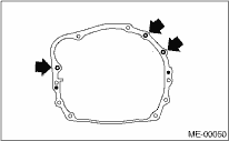
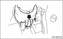
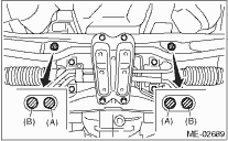
14. Tighten the nuts which install the front cushion rubber onto crossmember.
Tightening torque:
85 N·m (8.7 kgf-m, 62.7 ft-lb)
NOTE:
Make sure the front cushion rubber mounting bolts (A) and locator (B) are securely installed.
15. Install the ATF cooler pipe to frame. (AT model)
16. Install the front and center exhaust pipe. (DOHC Non-turbo model)
17. Install the center exhaust pipe. (DOHC Turbo model)
18. Lower the vehicle.
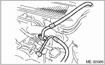
19. Connect the following hoses.
(1) Fuel delivery hose, return hose and evaporation hose
(2) Heater inlet and outlet hoses
(3) Brake booster vacuum hose
20. Connect the following connectors and terminals.
(1) Front oxygen (A/F) sensor connector (DOHC Non-turbo model)
(2) Rear oxygen (A/F) sensor connector (DOHC Non-turbo model)
(3) Engine ground terminal
(4) Engine harness connectors
(5) Generator connector & terminal
(6) A/C compressor connector
(7) Power steering switch connector
21. Install the air intake chamber stay. (DOHC Non-turbo model)
Tightening torque:
16 N·m (1.6 kgf-m, 11.6 ft-lb)
22. Tighten the engine ground cable.
Tightening torque:
14 N·m (1.4 kgf-m, 10.1 ft-lb)
23. Install the A/C pressure hoses.
NOTE:
Use new O-rings.
Tightening torque:
15 N·m (1.5 kgf-m, 10.8 ft-lb)
24. Install the secondary air pump.
25. Install the coolant filler tank. (DOHC Turbo model)
26. Install the radiator.
27. Install the intercooler. (DOHC Turbo model)
28. Install the air intake duct, air cleaner case and air intake chamber. (DOHC Non-turbo model)
29. Install the battery in the vehicle, and connect cables.
30. Refill engine coolant.
31. Check the ATF level and replenish it if necessary.
32. Charge the A/C system with refrigerant.
33. Install the collector cover. (DOHC Turbo model)
34. Remove the front hood stay, and close the front hood.
35. Lower the vehicle from the lift.