1. While the ABS sequence control is being performed, the operation of the hydraulic unit can be checked using the brake tester or pressure gauge after the hydraulic unit solenoid valve operation.
2. ABS sequence control can be started by diagnosis connector or Subaru Select Monitor.
1. ABS SEQUENCE CONTROL WITH SUBARU SELECT MONITOR
NOTE:
If a problem occurs, sequence control will not operate. In this case, diagnose the failure. 
1. Connect the Subaru Select Monitor to data link connector under the driver’s side instrument panel lower cover.
2. Turn the ignition switch to ON.
3. Subaru Select Monitor to ON.
4. Set the Subaru Select Monitor to “Brake Control” mode.
5. When the “Function check sequence” is selected, the “ABS sequence control” will start.
6. Execute the following operations when the message “Press the brake pedal so that the brake pedal force is between 100 and 150 kgf” is displayed.
(1) When using a brake tester, press the brake pedal pad with a force of 981 N (100 kgf, 221 lbf).
(2) When using a pressure gauge, press the brake pedal so that the pressure gauge indicates 3,432 kPa (35 kgf/cm2, 498 psi).
CAUTION:
On models with the hill holder feature, do not step on the clutch pedal.
7. “Press the [YES] key” will be displayed. Press the YES key.
8. The brake system being operated is displayed on the Subaru Select Monitor.
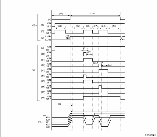
2. CONDITIONS FOR ABS SEQUENCE CONTROL
|
(1) |
Operation guide line of the sequence control |
(12) |
FR decompression valve |
(22) |
RR wheel cylinder pressure |
|
(2) |
Operation pattern of sequence control |
(13) |
FR compression valve |
(23) |
RL wheel cylinder pressure |
|
(3) |
Operating pressure of sequence control. |
(14) |
RR decompression valve |
(24) |
4 km/h (2 MPH) or less |
|
(4) |
All wheel speed |
(15) |
RR compression valve |
(25) |
10 km/h (6 MPH) or less |
|
(5) |
Ignition key |
(16) |
RL decompression valve |
(26) |
Approx. 2 seconds |
|
(6) |
ABS warning light |
(17) |
RL compression valve |
(27) |
1.0 second |
|
(7) |
Stop light switch |
(18) |
Pump motor |
(28) |
1.4 seconds |
|
(8) |
Point A |
(19) |
Master cylinder pressure |
(29) |
0.6 seconds |
|
(9) |
Valve relay |
(20) |
FL wheel cylinder pressure |
(30) |
Within 0.5 seconds |
|
(10) |
FL decompression valve |
(21) |
FR wheel cylinder pressure |
(31) |
0.4 seconds |
|
(11) |
FL compression valve |
NOTE:
• The sequence control operation starts from point A.
• HIGH indicates high voltage.
• LOW indicates low voltage.