1. Remove the manual transmission assembly from the vehicle. 
2. Remove the clutch release lever.
3. Remove the transfer case together with the extension case assembly.
4. Remove the bearing mounting bolts.
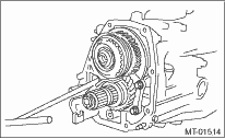
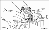
5. Remove the main shaft rear plate.
|
(A) |
Main shaft rear plate |
6. Separate the transmission case into the right and left cases by loosening the coupling bolts and nuts.
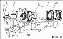
7. Remove the drive pinion shaft assembly from the left side of the transmission case and remove the main shaft assembly.
NOTE:
Use a hammer handle, etc. to remove if too tight.
|
(A) |
Main shaft ASSY |
|
(B) |
Drive pinion shaft ASSY |
8. Remove the differential assembly.
NOTE:
• Do not confuse the right and left roller bearing outer races.
• Be careful not to damage the oil seal of retainer.
1. Remove the manual transmission assembly from the vehicle.
2. Remove the clutch release lever.
3. Remove the transfer case together with the extension case assembly.
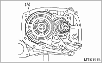
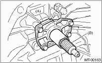
4. Remove the input shaft holder.
|
(A) |
Input shaft holder |
|
(B) |
Input shaft |
5. Remove the high-low switch.
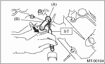
6. Use the ST to push out the straight pin and remove the high-low shifter lever.
| ST 398791700 | STRAIGHT PIN REMOVER 2 |
NOTE:
When pushing out the straight pin, push out in the direction away from the transmission case.
|
(A) |
Straight pin |
|
(B) |
High-low shifter lever |
7. Remove the main shaft rear plate.
|
(A) |
Main shaft rear plate |
8. Loosen the coupling bolt and 17 nuts, and separate the transmission case into right and left sides.
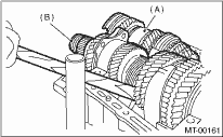
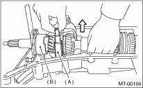
9. Using the butt of a hammer, etc. move aside the drive pinion shaft assembly, and remove the main shaft assembly from the left side of the transmission case.
|
(A) |
Main shaft ASSY |
|
(B) |
Drive pinion shaft ASSY |
10. Removal of the high-low shifter fork:
Remove the high-low shifter fork together with the high-low shifter shaft and washer.
NOTE:
Be careful not to drop the 2 high-low shifter pieces.
|
(A) |
High-low shifter fork |
|
(B) |
Input shaft assembly |
11. Remove the main shaft assembly and input shaft assembly.
NOTE:
The input shaft and main shaft will come apart, so make sure not to drop the assembly.
|
(A) |
Main shaft ASSY |
|
(B) |
Input shaft assembly |
12. Remove the differential assembly.
NOTE:
• Do not confuse the right and left roller bearing outer races.
• Be careful not to damage the oil seal of retainer.