NOTE:
Attach a cloth to the end of driven shaft (on the frictional side of thrust needle bearing) to prevent damage during disassembly or reassembly.
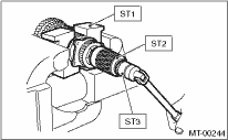
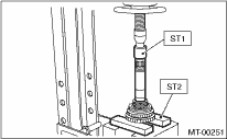
1. Flatten the tab of the axle nut. Remove the lock nut with ST1, ST2 and ST3.
| ST1 899884100 | HOLDER |
| ST2 498427100 | STOPPER |
| ST3 899988608 | SOCKET WRENCH (27) |
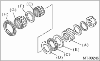
2. Draw out the drive pinion from driven shaft.
Remove the differential bevel gear sleeve, adjusting washer No. 1, adjusting washer No. 2, thrust bearing, needle bearing and drive pinion collar.
|
(A) |
Differential bevel gear sleeve |
|
(B) |
Adjusting washer No. 1 (25 × 37.5 × t) |
|
(C) |
Thrust bearing (25 × 37.5 × 3) |
|
(D) |
Adjusting washer No. 2 (25 × 37.5 × 4) |
|
(E) |
Needle bearing (25 × 30 × 20) |
|
(F) |
Drive pinion collar |
|
(G) |
Needle bearing (30 × 37 × 23) |
|
(H) |
Thrust bearing (33 × 50 × 3) |
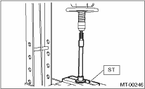
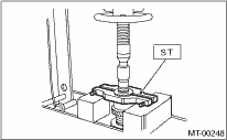
3. Remove the roller bearing and washer using ST and a press.
NOTE:
Do not reuse the roller bearing.
| ST 498077000 | REMOVER |
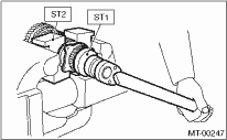
4. Flatten the tab of the axle nut. Remove the lock nut using ST1 and ST2.
| ST1 499987300 | SOCKET WRENCH (50) |
| ST2 899884100 | HOLDER |
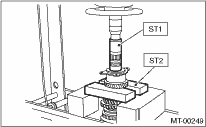
5. Remove the 5th driven gear using ST.
| ST 499857000 | 5TH DRIVEN GEAR REMOVER |
6. Remove the woodruff key.
7. Remove the roller bearing, 3rd — 4th driven gear using ST1 and ST2.
| ST1 499757002 | INSTALLER |
| ST2 899714110 | REMOVER |
8. Remove the key.
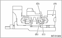
9. Remove the 2nd driven gear, inner baulk ring, synchro cone and outer baulk ring.
|
(A) |
2nd driven gear |
|
(B) |
Inner baulk ring |
|
(C) |
Synchro cone |
|
(D) |
Outer baulk ring |
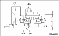
10. Remove the 1st driven gear, inner baulk ring, synchro cone, outer baulk ring, 2nd driven gear bushing, gear & hub assemblies using ST1 and ST2.
|
(A) |
1st driven gear |
|
(B) |
Inner baulk ring |
|
(C) |
Synchro cone |
|
(D) |
Outer baulk ring |
NOTE:
If necessary, use the new gear & hub assembly, when replacing the gear or hub assembly. Because these must engage at the specified point, avoid disassembly as much as possible. If it must be disassembled, mark the engaging point on the spline beforehand.
| ST1 499757002 | INSTALLER |
| ST2 899714110 | REMOVER |
11. Remove the sub gear for 1st driven gear. (Non-turbo model)