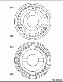
1. Assemble individual sleeve & hub assemblies.
|
(A) |
3rd-4th hub ASSY |
|
(B) |
3rd gear side |
|
(C) |
5th hub & sleeve No. 2 |
|
(D) |
5th gear side |
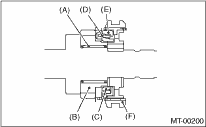
2. Install the 3rd drive gear, outer baulk ring, synchro cone, inner baulk ring, sleeve & hub assembly for the 3rd needle bearing, on the transmission main shaft.
NOTE:
Align the convex portion of baulk ring with the shifting insert.
|
(A) |
3rd needle bearing |
|
(B) |
3rd drive gear |
|
(C) |
Inner baulk ring |
|
(D) |
Synchro cone |
|
(E) |
Outer baulk ring |
|
(F) |
Sleeve & hub ASSY |
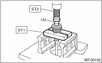
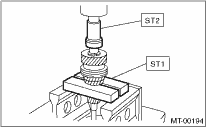
3. Install the 4th needle bearing race onto transmission main shaft using ST1, ST2 and press.
CAUTION:
Do not apply a load in excess of 10 kN (1 ton, 1.1 US ton, 1.0 Imp ton).
| ST1 899714110 | REMOVER |
| ST2 499877000 | RACE 4-5 INSTALLER |
|
(A) |
4th needle bearing race |
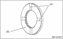
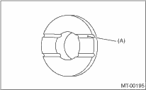
4. Install the baulk ring, needle bearing, 4th drive gear and 4th gear thrust washer to the transmission main shaft.
NOTE:
• Align the baulk ring and gear & hub assembly with key convex portion.
• Make sure the thrust washer is oriented in the correct direction.
|
(A) |
Groove |
|
(B) |
Face this surface to 4th gear side. |
5. Press-fit the ball bearing into the rear section of transmission main shaft using ST1, ST2 and a press.
CAUTION:
Do not apply a load in excess of 10 kN (1 ton, 1.1 US ton, 1.0 Imp ton).
| ST1 899714110 | REMOVER |
| ST2 499877000 | RACE 4-5 INSTALLER |
6. Using the ST1 and ST2, install the 5th gear thrust washer and 5th needle bearing race onto the rear section of transmission main shaft.
CAUTION:
Do not apply a load in excess of 10 kN (1 ton, 1.1 US ton, 1.0 Imp ton).
NOTE:
Make sure the thrust washer is oriented in the correct direction.
| ST1 899714110 | REMOVER |
| ST2 499877000 | RACE 4-5 INSTALLER |
|
(A) |
Face this surface to the 5th gear side. |
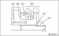
7. Install rest of the parts to the rear section of the transmission main shaft.
CAUTION:
• Attach the narrow side of the baulk lever to the 5th hub side.
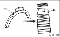
|
(A) |
Baulk lever |
|
(B) |
5th hub |
• Align the convex portion of baulk ring between the baulk lever.
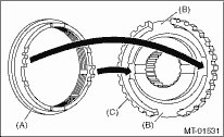
|
(A) |
Baulk ring |
|
(B) |
Baulk lever |
|
(C) |
5th hub |
|
(A) |
Needle bearing |
|
(B) |
5th drive gear |
|
(C) |
Baulk ring |
|
(D) |
5th hub & sleeve No. 2 |
|
(E) |
Lock washer |
|
(F) |
Lock nut |
8. Tighten the lock nuts to the specified torque using ST1 and ST2.
9. Crimp lock nuts in two locations after tightening.
| ST1 499987003 | SOCKET WRENCH |
| ST2 498937000 | TRANSMISSION HOLDER |
Tightening torque:
120 N·m (12.2 kgf-m, 88.5 ft-lb)