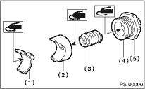
1. Apply a coat of grease to the inside and outside of the new oil seal.
Steering grease:
ONE LUBER MO (Part No. 003608001)
2. Verify the direction of the oil seal and installation position. Using the ST and a press, press-fit the oil seal into the gearbox.
| ST 34199AE130 | GEARBOX OIL SEAL INSTALLER |

|
(1) |
Oil seal |
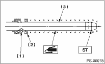
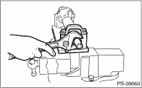
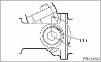
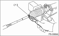
3. Attach the steering body to ST as shown in the figure. Apply a coat of grease to needle bearing.
| ST 926200000 | STAND |
CAUTION:
Make sure the needle bearing is free from defects. If it is faulty, replace the steering body with a new part.
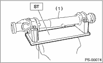
|
(1) |
Steering body |
4. Using the ST B and ST C, attach the oil seal to ST A.
| ST 927490000 | INSTALLER A, B, C |
NOTE:
Face the oil seal in the direction as shown in the figure.
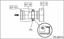
|
(A) |
Oil seal |
5. Insert the ST A with oil seal assembled from the gear side of rack. Remove the oil seal from ST A near piston, and then remove the ST A from rack.
|
(A) |
Oil seal |
|
(B) |
Rack |
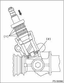
|
(C) |
Piston |
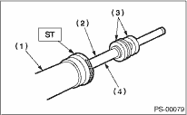
6. Install the back-up washer from the gear side of rack.
|
(1) |
Oil seal |
|
(2) |
Back-up washer |
|
(3) |
Rack |
7. Attach the ST on rack, equally apply a thin coat of grease to the rack and ST, and then install the oil seal.
| ST 926250000 | GUIDE |
CAUTION:
Be careful not to scratch the oil seal lips with the inner ring section of piston.
|
(1) |
Rack piston inner ring |
|
(2) |
Outer side oil seal |
|
(3) |
Rack |
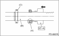
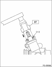
8. Apply a coat of grease to the grooves in rack, sliding surface of sleeve and sealing surface of piston. Attach the ST on the end of steering body cylinder. Then insert the rack into steering body from cylinder side.
| ST 34199AE000 | GUIDE (OIL SEAL) |
CAUTION:
Do not allow grease to block the air vent hole on rack.
|
(1) |
Cylinder side of steering body |
|
(2) |
Air vent hole |
|
(3) |
Oil seal |
|
(4) |
Rack |
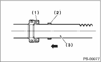
9. Slowly push the inner side oil seal using the press until the distance from the ST to the end of the rack is 65 mm (2.56 in).
| ST 34199AE000 | GUIDE (OIL SEAL) |
CAUTION:
Make sure that there are no scratches on the inner wall of the ST. Otherwise there is a possibility of the oil seal being damaged when it is installed.
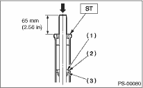
|
(1) |
Rack piston |
|
(2) |
Inner side oil seal |
|
(3) |
Back-up ring |
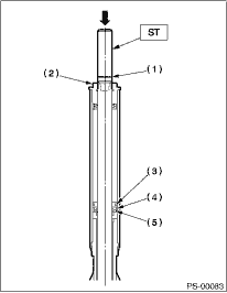
10. Make the ST2 and pipe pass through rack, and then press-in the ST1, ST 2 and the outer side oil seal using a press.
| ST1 34199AE000 | GUIDE (OIL SEAL) |
| ST2 34199AE010 | INSTALLER (OIL SEAL) |
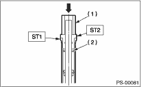
|
(1) |
Pipe |
|
(2) |
Outer side oil seal |
11. Install a new holder to the cylinder side of steering body.
Tightening torque:
64 N·m (6.5 kgf-m, 47.2 ft-lb)
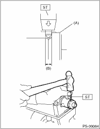
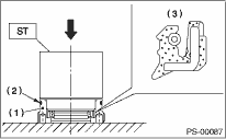
12. Attach the ST on rack cylinder. Using the press, press in the ST until the groove on the ST aligns with the edge of the holder.
| ST 34199FE000 | INSTALLER & REMOVER |
|
(1) |
Groove |
|
(2) |
Holder |
|
(3) |
Rack piston |
|
(4) |
Oil seal |
|
(5) |
Back-up ring |
13. Using the ST, crimp the steering body at one point less than 3 mm (0.12 in) from holder.
CAUTION:
Be careful not to deform the holder.
| ST 34099FA060 | PUNCH HOLDER |
|
(A) |
Holder |
|
(B) |
3 mm (0.12 in) |
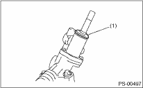
14. Roll a vinyl tape on the serration portion of valve assembly, and then apply grease on the tape surface.
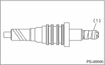
|
(1) |
Vinyl tape |
15. Apply a coat of grease on the gear teeth of the valve assembly, and then attach the valve assembly taking care not to scratch oil seal and seal ring.
|
(1) |
Seal ring |
|
(2) |
Oil seal |
16. Apply grease on the oil seal circumference, and then press it into the plug using ST and a press. Replace the O-rings of plug circumference with new O-rings.
| ST 34199AE110 | OIL SEAL PLUG INSTALLER |
CAUTION:
Install the oil seal paying attention to correct direction.
|
(1) |
Plug |
|
(2) |
O-ring |
|
(3) |
Oil seal |
17. Attach the plug using ST.
| ST 34199AE090 | PLUG WRENCH |
Tightening torque:
64 N·m (6.5 kgf-m, 47.2 ft-lb)
|
(1) |
Plug |
18. Attach the dust cover, and remove the vinyl tape.
|
(1) |
Dust cover |
19. Temporarily tighten the tie-rod to the rack end, and then operate the rack from lock to lock for two or three times to make it fit in. Remove any grease blocking the air vent hole.
CAUTION:
Operating the rack from lock to lock without installing tie-rods may damage the oil seal. Always install the LEFT AND RIGHT tie-rods.
20. Apply a coat of grease to the sliding surface of seat pad, sleeve and seating surface of spring, and then insert sleeve into the steering body.
Charge the adjusting screw with grease, and then insert the spring into adjusting screw. Then install on the steering body.
|
(1) |
Sheet pad |
|
(2) |
Sleeve |
|
(3) |
Spring |
|
(4) |
Adjusting screw |
|
(5) |
Lock nut |
21. Tighten the adjusting screw to the specified torque.
Tightening torque:
7.4 N·m (0.75 kgf-m, 5.4 ft-lb)
NOTE:
After tightening with the specified torque, loosen it by 25°.
22. Remove the tie-rod.
23. Check that the play, or looseness, is at the standard value.

24. Loosen the adjusting screw, and then apply liquid gasket to at least 1/3 of the entire perimeter of adjusting screw thread.
Liquid gasket
THREE BOND 1141
|
(1) |
Apply liquid gasket to at least 1/3 of entire perimeter. |
25. Tighten the adjusting screw.
(1) Tighten the adjusting screw to the specified torque, then loosen it.
Tightening torque:
9.8 N·m (1.0 kgf-m, 7.2 ft-lb)
(2) Tighten the adjusting screw to the specified torque, then loosen it.
Tightening torque:
4.9 N·m (0.50 kgf-m, 3.6 ft-lb)
(3) Tighten the adjusting screw to the specified torque, then loosen it 26°.
Tightening torque:
4.9 N·m (0.50 kgf-m, 3.6 ft-lb)
NOTE:
After tightening with the specified torque, loosen it by 25°.
26. Install the lock nut. While holding the adjusting screw with a wrench, tighten the lock nut using ST.
| ST 926230000 | SPANNER |
Tightening torque (lock nut):
39 N·m (4.0 kgf-m, 28.9 ft-lb)
NOTE:
Hold the adjusting screw with a wrench to prevent it from turning while tightening the lock nut.
27. Install the tie-rod into rack.
Tightening torque:
90 N·m (9.2 kgf-m, 66 ft-lb)
NOTE:
Check the mating face of rack and tie-rod for foreign matter such as dust etc.
28. Apply a coat of grease to the tie-rod groove, and then install the boot to the housing.
NOTE:
Make sure that the boot is installed without unusual inflation or deflation.
29. Crimp the boot so that the clearance of the boot band crimp portion becomes 2 mm (0.08 in) or less.
NOTE:
Use a new band.
|
(A) |
Boot band |
|
(B) |
2 mm (0.08 in) or less |
30. Fix the boot end with small clip.
|
(1) |
Clip |
31. After installing, check that the boot end is installed to the groove of the tie-rod.
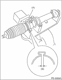
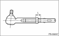
32. If the tie-rod end has been removed, screw in lock nut and tie-rod end to the screwed portion of tie-rod, and tighten the lock nut temporarily in a position as shown in the figure.
Installed tie-rod length L:
31.2 mm (1.23 in)
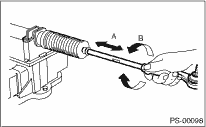
33. Inspect the gearbox as follows:
“A” Holding the tie-rod end, repeat lock to lock two or three times as quickly as possible.
“B” Holding the tie-rod end, turn it slowly at a radius one or two times as large as possible.
Finally, make sure that the boot is installed in the specified position without inflating.
34. Remove the gearbox from ST.
| ST 926200000 | STAND |