CAUTION:
Use gloves to avoid damage and getting fingerprints on the glass surface and meter surfaces.
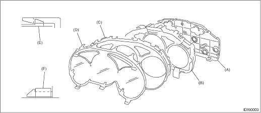
1. Disengage the claw (E) to remove case (B) from back cover (A).
2. Disengage claw (F) to remove meter glass (D) and reflector (C) from the inner case.
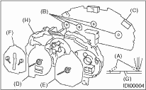
3. Pull up claw (A) in portion (B) of combination meter printed circuit (C) with combination pliers. Push out the speedometer (D) and tachometer (E) and engine coolant temperature gauge & fuel gauge assembly (F) using the hole (G).
4. Pull up the claw in the center of the combination meter printed circuit (C), and remove the printed circuit from case (H).
|
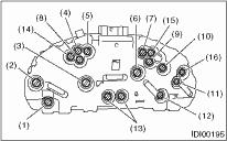
(1) |
Charge indicator light |
|
(2) |
Tachometer |
|
(3) |
Speedometer & tachometer |
|
(4) |
HI-beam indicator light |
|
(5) |
Turn signal indicator light (Right) |
|
(6) |
Speedometer |
|
(7) |
Turn signal indicator light (Left) |
|
(8) |
Vehicle dynamics control (VDC) indicator |
|
(9) |
Brake warning light |
|
(10) |
ABS warning light |
|
(11) |
Fuel gauge |
|
(12) |
Engine coolant temperature gauge |
|
(13) |
LCD (Outside temperature display, odometer tripmeter, and select indicator.) |
|
(14) |
Rear fog light indicator light |
|
(15) |
Rear differential oil temperature warning light |
|
(16) |
Power mode indicator light |