|
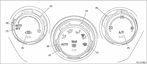
(1) |
Defroster switch |
(4) |
A/C switch |
(7) |
OFF switch |
|
(2) |
Rear window defogger switch |
(5) |
Fan dial |
(8) |
Temperature adjustment dial |
|
(3) |
Air flow control dial |
(6) |
FRESH/RECIRC switch |
(9) |
AUTO switch |
1. A/C CONTROL PANEL SELF-DIAGNOSIS

NOTE:
When the sunload sensor check is performed indoors or in the shade, it could be diagnosed as having an open circuit. Always check the sunload sensor at a location exposed to direct sunlight.
|
Air flow control dial position |
Fan dial position |
Sensor |
No trouble |
Short circuit |
Open circuit |
When currently malfunctioning |
When having malfunctioned in the past |
|
AUTO |
AUTO |
In-vehicle sensor |
FRESH/RECIRC switch LED is turned off |
FRESH/RECIRC switch LED blinks (Illuminates for 0.2 sec ⇔ turns off for 0.2 sec.) |
FRESH/RECIRC switch LED blinks (Illuminates for 1 sec ⇔ turns off for 1 sec.) |
Rear window defogger switch LED is turned off |
Rear window defogger switch LED illuminates |
|
1st |
Ambient sensor |
FRESH/RECIRC switch LED blinks (Illuminates for 0.2 sec ⇔ turns off for 0.2 sec.) | |||||
|
2nd |
Evaporator sensor |
FRESH/RECIRC switch LED blinks (Illuminates for 0.2 sec ⇔ turns off for 0.2 sec.) | |||||
|
3rd |
Engine coolant temperature sensor |
— | |||||
|
4th |
Sunload sensor |
FRESH/RECIRC switch LED blinks (Illuminates for 0.2 sec ⇔ turns off for 0.2 sec.) | |||||
|
5th – 7th |
CAN communication |
— |
|
Operation |
Fan dial position | |||||||
|
AUTO |
1st |
2nd |
3rd |
4th |
5th |
6th |
7th | |
|
Blower fan |
4 V |
4 V |
4.9 V |
5.9 V |
7.0 V |
8.3 V |
9.8 V |
14 V |
|
FRESH/RECIRC door |
RECIRC |
RECIRC |
MIX |
FRESH |
FRESH |
FRESH |
FRESH |
FRESH |
|
Air flow control door |
FACE |
FACE |
FACE |
B/L |
HEAT |
HEAT |
D/H |
DEF |
|
Air mix door |
0% |
0% |
0% |
50% |
50% |
100% |
100% |
100% |
|
A/C compressor |
OFF |
ON |
ON |
ON |
ON |
ON |
ON |
ON |
|
PTC heater (Diesel engine model only) |
OFF |
OFF |
OFF |
ON (mini PTC heater) |
ON (mini PTC heater) |
ON (PTC heater 1) |
ON (PTC heater 2) |
ON (PTC heater 2) |
|
Air flow control dial position |
Fan dial position |
Drive signal to check |
A/C switch LED |
No trouble |
Short circuit |
Open circuit |
When currently malfunctioning |
When having malfunctioned in the past |
|
FACE |
AUTO |
MIX #1 |
Blinking (Illuminates for 0.2 sec ⇔ turns off for 0.2 sec.) |
FRESH/RECIRC switch LED is illuminated |
FRESH/RECIRC switch LED blinks (Illuminates for 0.2 sec ⇔ turns off for 0.2 sec.) |
FRESH/RECIRC switch LED blinks (Illuminates for 1 sec ⇔ turns off for 1 sec.) |
Rear window defogger switch LED is turned off |
Rear window defogger switch LED illuminates |
|
1st |
MIX #2 | |||||||
|
2nd |
MIX #3 | |||||||
|
3rd — 7th |
MIX #4 | |||||||
|
AUTO |
MODE #1 |
Blinking (Illuminates for 1 sec ⇔ turns off for 1 sec.) | ||||||
|
1st |
MODE #2 | |||||||
|
2nd |
MODE #3 | |||||||
|
3rd — 7th |
MODE #4 |