1.CHECK POWER SUPPLY FOR INTAKE DOOR ACTUATOR.
1) Turn the ignition switch to OFF.
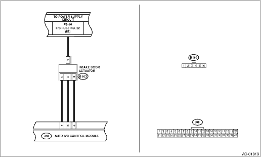
2) Disconnect the intake door actuator connector.
3) Turn the ignition switch to ON.
4) Measure the voltage between intake door actuator connector and chassis ground.
Connector & terminal
(B163) No. 1 (+) — Chassis ground (−):
|
Is the voltage 7 V (at normal temperature)?
|
|
Check for open or short circuit in the harness between intake door actuator and fuse.
|
2.CHECK HARNESS BETWEEN AUTO A/C CONTROL MODULE AND INTAKE DOOR ACTUATOR.
1) Turn the ignition switch to OFF.
2) Disconnect the auto A/C control module connector.
3) Measure the resistance between intake door actuator connector and auto A/C control module connector.
Connector & terminal
(i88) No. 8 — (B163) No. 6:
(i88) No. 7 — (B163) No. 5:
(i88) No. 6 — (B163) No. 4:
|
Is the resistance less than 1 Ω?
|
|
Repair the harness between auto A/C control module and intake door actuator.
|
3.CHECK OPERATION OF INTAKE DOOR ACTUATOR.
1) Connect the intake door actuator connector.
2) Disconnect the auto A/C control module connector.
3) Ground the auto A/C control module connector with a suitable wire.
4) Turn the ignition switch to ON, and check the operation of intake door actuator.
Connector & terminal
(B163) No. 4 — Chassis ground:
|
Does the actuator move to the FRESH side?
|
|
Replace the intake door actuator.
|
4.CHECK OPERATION OF INTAKE DOOR ACTUATOR.
1) Turn the ignition switch to OFF.
2) Ground the auto A/C control module connector with a suitable wire.
3) Turn the ignition switch to ON, and check the operation of intake door actuator.
Connector & terminal:
(B163) No. 1 — Chassis ground:
|
Does the actuator move to the RECIRC side?
|
Replace the auto A/C control module. 
|
Replace the intake door actuator.
|