1.CHECK POWER SUPPLY FOR MODE DOOR ACTUATOR.
1) Turn the ignition switch to OFF.
2) Disconnect the mode door actuator connector.
3) Turn the ignition switch to ON.
4) Measure the voltage between the mode door actuator connector terminal and chassis ground.
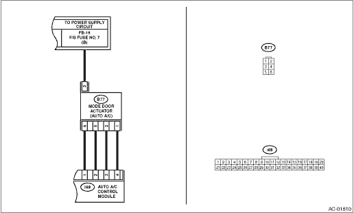
Connector & terminal
(B77) No. 3 (+) — Chassis ground (−):
|
Is the voltage approx. 10 V or more?
|
|
Check the DC power supply circuit.
|
2.CHECK MODE DOOR ACTUATOR.
1) Disconnect the mode door actuator connector.
2) Use a tester to measure the resistance between mode door actuator terminals.
|
Is the resistance between 80 — 100 Ω?
|
|
Replace the mode door actuator.
|
3.CHECK HARNESS BETWEEN AUTO A/C CONTROL MODULE AND MODE DOOR ACTUATOR.
1) Turn the A/C and ignition switch to OFF.
2) Disconnect the auto A/C control module connector.
3) Measure the resistance between auto A/C control module and mode door actuator connector.
Connector & terminal
(B77) No. 1 — (i88) No. 4:
(B77) No. 2 — (i88) No. 3:
(B77) No. 5 — (i88) No. 2:
(B77) No. 6 — (i88) No. 1:
|
Is the resistance less than 1 Ω?
|
|
Repair the harness between auto A/C control module and mode door actuator.
|
4.CHECK POOR CONTACT.
Check poor contact of auto A/C control module and connector.
|
Is there poor contact of connector?
|
|
Replace the auto A/C control module. 
|