1.CHECK SHIFT LOCK SOLENOID.
1) Force start the integrated unit, and check the operation of shift lock solenoid. 
2) Operate the select lever without depressing the brake pedal.
|
Does the select lever operate?
|
|
|
2.CHECK OUTPUT SIGNAL OF INTEGRATED UNIT.
1) Using the Subaru Select Monitor, display the following items.
• Key-lock warning SW
• Shift Position
• P SW
• Stop Light Switch
2) Step on the brake and shift the select lever to “P” range.
|
Do the units of measure of items displayed change?
|
|
Check the circuits of the items whose values do not change.
|
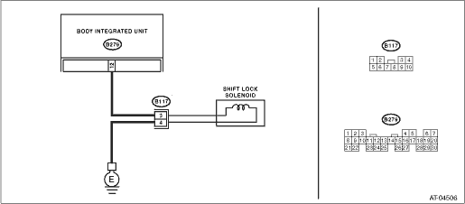
3.CHECK HARNESS CONNECTOR BETWEEN BODY INTEGRATED UNIT AND SHIFT LOCK SOLENOID.
Measure the harness resistance between the body integrated unit and chassis ground.
Connector & terminal
(B279) No. 12 — Chassis ground:
|
Is the resistance 1 MΩ or more?
|
|
Repair the short circuit of harness between body integrated unit and shift lock solenoid connector.
|
4.CHECK HARNESS BETWEEN SHIFT LOCK SOLENOID AND CHASSIS GROUND TERMINAL.
Measure the resistance of harness between shift lock solenoid and chassis ground.
Connector & terminal
(B117) No. 4 — Chassis ground:
|
Is the resistance less than 1 Ω?
|
|
Repair the open circuit of harness between chassis ground and shift lock solenoid connector.
|
5.CHECK SHIFT LOCK SOLENOID.
Measure the resistance of shift lock solenoid terminals.
|
Is the resistance 7 — 21 Ω?
|
|
Replace the shift lock solenoid.
|
6.CHECK OUTPUT SIGNAL OF BODY INTEGRATED UNIT.
1) Connect all connectors.
2) Turn the ignition switch to ON.
3) Set the select lever to the “D” range while stepping on the brake pedal.
4) Measure the voltage between body integrated unit and chassis ground.
Connector & terminal
(B279) No. 12 (+) — Chassis ground (−):
|
Is the voltage 10.5 V or more?
|
|
|
7.CHECK OUTPUT SIGNAL OF BODY INTEGRATED UNIT.
3) Set the select lever to the “D” range and slowly increase vehicle speed to above 20 km/h (12 MPH).
NOTE:
The speed difference between the front and rear wheels will illuminate the ABS warning light or VDC warning light, but this does not indicate a malfunction. If the warning light illuminates, delete the ABS or VDC memory after completing the AT control diagnosis.
4) Measure the voltage between body integrated unit and chassis ground.
Connector & terminal
(B279) No. 12 (+) — Chassis ground (−):
|
Is the voltage less than 1 V?
|
Check for poor contact in the reverse inhibitor control circuit harness or connectors, and repair the fault location.
|
|
8.CHECK FOR POOR CONTACT.
|
Is there poor contact in the reverse inhibitor control circuit?
|
|
Replace the body integrated unit.
|