1.CHECK INSTALLATION OF TCM CONNECTOR.
Turn the ignition switch to OFF.
|
Is TCM connector connected to TCM?
|
|
Connect the TCM connector to TCM.
|
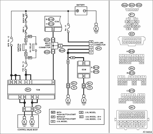
2.CHECK SUBARU SELECT MONITOR POWER SUPPLY CIRCUIT..
Measure the voltage between data link connector and chassis ground.
Connector & terminal
(B40) No. 16 (+) — Chassis ground (−):
|
Is the voltage 10 V or more?
|
|
Repair harness connector between the battery and data link connector, and poor contact of the connector.
|
3.CHECK SUBARU SELECT MONITOR GROUND CIRCUIT.
1) Disconnect the connectors from the ECM.
2) Measure the resistance of harness between data link connector and ECM.
Connector & terminal
2.0 L model
(B40) No. 4 — (B136) No. 33:
(B40) No. 5 — (B136) No. 33:
2.5 L model
(B40) No. 4 — (B136) No. 6:
(B40) No. 5 — (B136) No. 6:
|
Is the resistance less than 1 Ω?
|
|
Repair the open circuit of harness between data link connector and ECM.
|
4.CHECK SUBARU SELECT MONITOR GROUND CIRCUIT.
Measure the resistance of harness between data link connector and chassis ground.
Connector & terminal
(B40) No. 16 — Chassis ground:
|
Is the resistance 1 MΩ or more?
|
|
Repair the short circuit of harness between data link connector and ground terminals.
|
5.CHECK ENGINE GROUND CIRCUIT.
Check the engine ground circuit.
|
Is the engine ground circuit normal?
|
|
Repair ground circuit of ECM.
|
6.CHECK COMMUNICATION OF SUBARU SELECT MONITOR.
1) Turn the ignition switch to ON.
2) Check the communication with the transmission.
|
Is the name of system displayed on Subaru Select Monitor?
|
|
|
7.CHECK COMMUNICATION OF SUBARU SELECT MONITOR.
1) Turn the ignition switch to OFF.
2) Disconnect the TCM connector.
3) Turn the ignition switch to ON.
4) Check the communication with the engine system.
|
Is the name of system displayed on Subaru Select Monitor?
|
|
|
8.CHECK OUTPUT SIGNAL OF TCM.
1) Turn the ignition switch to OFF.
2) Connect the connector to the TCM.
3) From the data link connector (B40) No. 7, disconnect the connectors of control modules other than the TCM and ECM.
CAUTION:
When disconnecting the connector from airbag control module, always follow the precautions on AB section. 
4) Turn the ignition switch to ON.
5) Check the communication with the transmission system.
|
Is the name of system displayed on Subaru Select Monitor?
|
Check each control module.
|
|
9.CHECK HARNESS CONNECTOR BETWEEN EACH CONTROL MODULE AND DATA LINK CONNECTOR.
1) Turn the ignition switch to OFF.
2) From the data link connector (B40) No. 7, disconnect the connectors of all control modules.
3) Measure the resistance between TCM connector and chassis ground.
Connector & terminal
(B40) No. 7 — Chassis ground:
|
Is the resistance 1 MΩ or more?
|
|
Check harness and connector between each control module and data link connector.
|
10.CHECK OUTPUT SIGNAL OF TCM.
1) Turn the ignition switch to ON.
2) Measure the voltage between TCM and chassis ground.
Connector & terminal
(B40) No. 7 (+) — Chassis ground (−):
|
Is the voltage 1 V or more?
|
Check harness and connector between each control module and data link connector.
|
|
11.CHECK HARNESS CONNECTOR BETWEEN TCM AND DATA LINK CONNECTOR.
Measure the resistance between TCM connector and data link connector.
Connector & terminal
(B40) No. 7 — (B54) No. 8:
|
Is the resistance less than 1 Ω?
|
|
Repair the harness and connector between TCM and data link connector.
|
12.CHECK INSTALLATION OF TRANSMISSION HARNESS CONNECTOR.
|
Is the transmission harness connector connected to bulkhead harness connector?
|
|
Connect the bulkhead harness connector to transmission harness connector.
|
13.CHECK POOR CONTACT OF CONNECTORS.
|
Is there poor contact in control module power supply and data link connector?
|
|
|
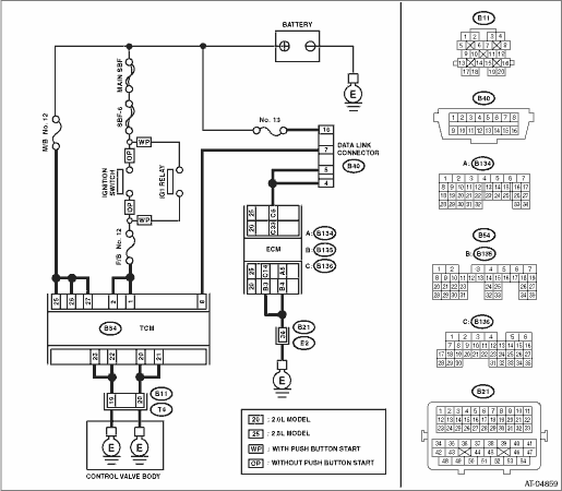
14.CHECK TCM POWER SUPPLY.
1) Disconnect the connector from TCM.
2) Turn the ignition switch to ON.
3) Measure the voltage between TCM connector and chassis ground.
Connector & terminal
(B54) No. 25 (+) — Chassis ground (−):
(B54) No. 26 (+) — Chassis ground (−):
(B54) No. 27 (+) — Chassis ground (−):
|
Is the voltage 10 — 13 V?
|
|
|
15.CHECK M/B FUSE (NO. 12).
1) Turn the ignition switch to OFF.
2) Remove the fuse (No. 12).
|
Is the fuse (No. 12) blown out?
|
Replace the fuse. If the replaced fuse blows out easily, repair the short circuit in the harness between the fuse and the TCM.
|
Repair the open circuit of harness between the fuse and the TCM, or the fuse and battery, and poor contacts of connectors.
|
16.CHECK IGNITION POWER SUPPLY CIRCUIT.
1) Turn the ignition switch to ON.
2) Measure the ignition power supply voltage between TCM connector and chassis ground.
Connector & terminal
(B54) No. 1 (+) — Chassis ground (−):
(B54) No. 2 (+) — Chassis ground (−):
|
Is the voltage 10 — 13 V?
|
|
|
17.CHECK F/B FUSE (NO. 12).
Remove the fuse (No. 12).
|
Is the fuse (No. 12) blown out?
|
Replace the fuse. If the replaced fuse blows out easily, repair the short circuit in the harness between the fuse and the TCM.
|
Repair the open circuit of harness between the fuse and the TCM, or the fuse and battery, and poor contacts of connectors.
|
18.CHECK HARNESS CONNECTOR BETWEEN TCM AND TRANSMISSION.
1) Turn the ignition switch to OFF.
2) Disconnect the connectors from TCM and transmission.
3) Measure the resistance of harness between TCM and transmission connector.
Connector & terminal
(B54) No. 20 — (B11) No. 20:
(B54) No. 21 — (B11) No. 20:
(B54) No. 22 — (B11) No. 19:
(B54) No. 23 — (B11) No. 19:
|
Is the resistance less than 1 Ω?
|
|
Repair the open circuit of harness between TCM and transmission harness connector, and poor contact of connector.
|
19.CHECK HARNESS CONNECTOR BETWEEN TRANSMISSION AND TRANSMISSION GROUND.
Measure the resistance of the harness between transmission and transmission ground.
Connector & terminal
(T4) No. 19 — Transmission ground:
(T4) No. 20 — Transmission ground:
|
Is the resistance less than 1 Ω?
|
|
Repair the open circuit of the harness between transmission and transmission ground.
|
20.CHECK POOR CONTACT OF CONNECTORS.
|
Is there poor contact in TCM power supply, ground and data link connector?
|
|
Replace the TCM.
|