DIAGNOSIS:
• LED does not illuminate even if FWD switch is ON.
• FWD signal circuit is open or shorted.
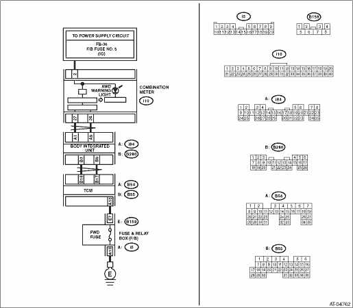
WIRING DIAGRAM:

| STEP | CHECK | YES | NO |
|
Is the spare fuse OK? |
|
Replace the fuse. |
|
|
When the fuse is inserted to FWD switch, does the LED illuminate? |
|
|
|
|
Does the AWD warning light illuminate? |
Check the SPORT shift switch. |
|
|
|
Is the resistance less than 1 Ω? |
|
Repair the open circuit of harness between TCM and FWD switch connectors. |
|
|
Is the resistance less than 1 Ω? |
|
Repair the open circuit of harness between FWD switch connector and chassis ground. |
|
|
Is the resistance 1 MΩ or more? |
|
Repair the short circuit of harness between TCM and FWD switch connectors. |
|
|
Is the voltage less than 1 V? |
|
|
|
|
Is the voltage 10.5 V or more? |
|
Replace the TCM. |
|
|
Is DTC of CAN communication displayed? |
Perform diagnosis according to the DTC. |
|
|
|
Is the AWD warning light OK? |
|
Replace the combination meter assembly. |
|
|
Is there poor contact in FWD switch circuit? |
Repair the poor contact. |
Replace the TCM. |
