1. COMMUNICATION FOR INITIALIZING IMPOSSIBLE
DETECTING CONDITION:
Defective harness connector
TROUBLE SYMPTOM:
Communication is impossible between VDC and Subaru Select Monitor.
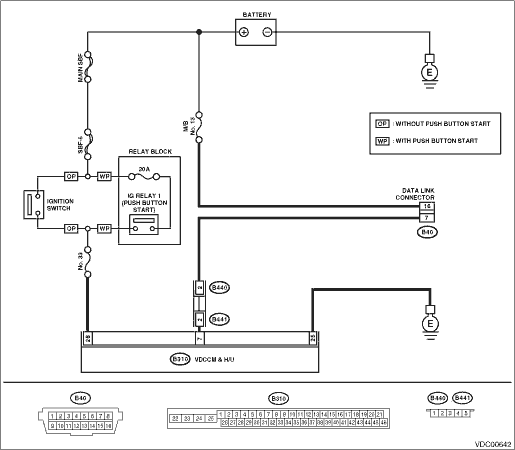
WIRING DIAGRAM:
• LHD model

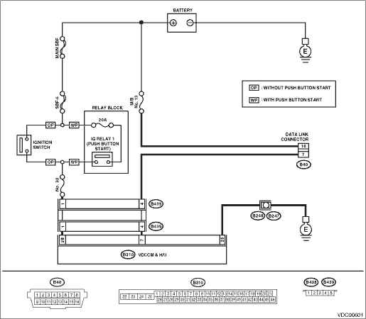
• RHD model
| STEP | CHECK | YES | NO |
|
Is the ignition switch ON? |
|
Turn the ignition switch to ON, and select VDC mode using Subaru Select Monitor. |
|
|
Is the voltage 11 V or more? |
|
Charge or replace the battery. |
|
|
Is there poor contact at the battery terminal? |
Repair or tighten the battery terminal. |
|
|
|
Is the system name displayed on Subaru Select Monitor? |
|
|
|
|
Is the system name displayed on Subaru Select Monitor? |
Replace the VDCCM&H/U. |
|
|
|
Is the resistance 1 MΩ or more? |
|
Repair the harness and connector between each control module and data link connector. |
|
|
Is the voltage less than 1 V? |
|
Repair the harness and connector between each control module and data link connector. |
|
|
Is the resistance less than 0.5 Ω? |
|
Repair harness and connector between VDCCM&H/U and data link connector. |
|
|
Is the VDCCM&H/U connector inserted into VDCCM&H/U until the clamp locks onto it? |
|
Insert VDCCM&H/U connector into VDCCM&H/U. |
|
|
Is the voltage 10 — 15 V? |
|
Repair open circuit in harness between VDCCM&H/U and battery. |
|
|
Is the resistance less than 0.5 Ω? |
|
Repair the open circuit of VDCCM&H/U ground harness and poor contact of connector. |
|
|
Is there poor contact in control module power supply, ground circuit and data link connector? |
Repair the connector. |
Replace the VDCCM only. |
