1.CHECK VDCCM&H/U INPUT VOLTAGE.
1) Turn the ignition switch to OFF.
2) Disconnect the connector from the VDCCM&H/U.
3) Run the engine at idle.
4) Measure the voltage between VDCCM&H/U connector and chassis ground.
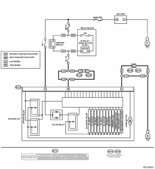
Connector & terminal
(B310) No. 28 (+) — Chassis ground (−):
(B310) No. 24 (+) — Chassis ground (−):
|
Is the voltage 10 — 15 V?
|
|
Repair the power supply circuit.
|
2.CHECK VDCCM&H/U INPUT VOLTAGE.
Calculate the voltage difference measured in step 1.
A: (B310) No. 28 (+) — Chassis ground (−):
B: (B310) No. 24 (+) — Chassis ground (−):
|
Is the voltage difference between A and B 2 V or more?
|
Repair the power supply circuit.
|
|
3.CHECK VDCCM&H/U GROUND CIRCUIT.
1) Turn the ignition switch to OFF.
2) Measure the resistance between VDCCM&H/U connector and chassis ground.
Connector & terminal
(B310) No. 25 — Chassis ground:
|
Is the resistance less than 0.5 Ω?
|
|
Repair the VDCCM&H/U ground harness.
|
4.CHECK VDCCM&H/U VALVE RELAY.
Measure the resistance between VDCCM&H/U connector terminals.
Connector & terminal
(B310) No. 24 — (B310) No. 25:
|
Is the resistance 1 MΩ or more?
|
|
|
5.CHECK POOR CONTACT OF CONNECTORS.
|
Is there poor contact of connector between generator, battery and VDCCM&H/U?
|
|
|
6.CHECK VDCCM&H/U.
1) Connect all connectors.
2) Clear the memory. 
3) Perform the Inspection Mode.
|
Is the same DTC displayed?
|
Replace the VDCCM only.
|
|
7.CHECK OTHER DTC DETECTION.
|
Is any other DTC displayed?
|
Perform the diagnosis according to DTC.
|
Temporary poor contact occurs.
|