1.CHECK VDCCM&H/U INPUT VOLTAGE.
1) Turn the ignition switch to OFF.
2) Disconnect the connector from the VDCCM&H/U.
3) Turn the ignition switch to ON.
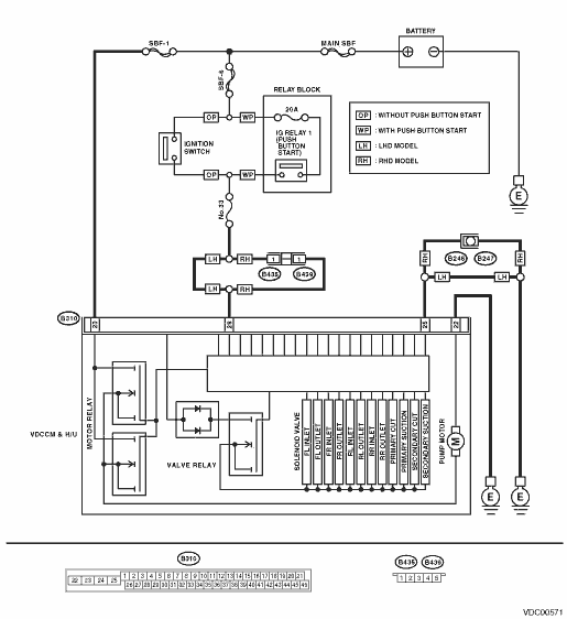
4) Measure the voltage between VDCCM&H/U connector and chassis ground.
Connector & terminal
(B310) No. 23 (+) — Chassis ground (−):
(B310) No. 28 (+) — Chassis ground (−):
|
Is the voltage 10 — 15 V?
|
|
Repair the VDCCM&H/U power supply circuit.
|
2.CHECK INSTALLATION OF MOTOR GROUND.
|
Is the motor ground terminal installation bolt tightened 33 N·m (3.4 kgf-m, 24.3 ft-lb)?
|
|
Tighten the motor ground terminal attachment bolts.
|
3.CHECK VDCCM&H/U GROUND CIRCUIT.
1) Turn the ignition switch to OFF.
2) Measure the resistance between VDCCM&H/U connector and chassis ground.
Connector & terminal
(B310) No. 25 — Chassis ground:
(B310) No. 22 — Chassis ground:
|
Is the resistance less than 0.5 Ω?
|
|
Repair the VDCCM&H/U ground harness.
|
4.CHECK VDCCM&H/U MOTOR RELAY.
Measure the resistance between VDCCM&H/U connector terminals.
|
Is the resistance 1 MΩ or more?
|
|
|
5.CHECK POOR CONTACT OF CONNECTORS.
Turn the ignition switch to OFF.
|
Is there poor contact of connector between generator, battery and VDCCM&H/U?
|
|
|
6.CHECK VDCCM&H/U.
1) Connect all connectors.
2) Clear the memory. 
3) Perform the Inspection Mode.
|
Is the same DTC displayed?
|
Replace the VDCCM&H/U.
|
|
7.CHECK OTHER DTC DETECTION.
|
Is any other DTC displayed?
|
Perform the diagnosis according to DTC.
|
Temporary poor contact occurs.
NOTE:
Though the ABS warning light remains on at this time, this is normal. Drive the vehicle at 12 km/h (7 MPH) or more in order to turn ABS warning light off. Be sure to drive the vehicle and check that the warning light goes off.
|