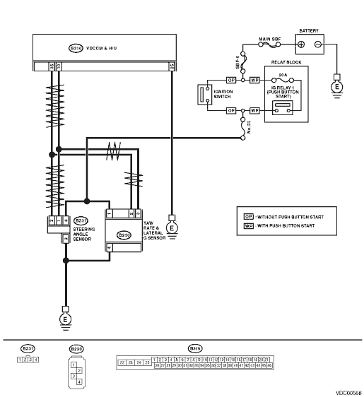
1.CHECK YAW RATE & LATERAL G SENSOR POWER SUPPLY.
1) Turn the ignition switch to OFF.
2) Disconnect the connector from yaw rate & lateral G sensor.
3) Turn the ignition switch to ON.
4) Measure the voltage between yaw rate & lateral G sensor and chassis ground.
Connector & terminal
(B230) No. 1 (+) — Chassis ground (−):
|
Is the voltage 10 — 15 V?
|
|
Repair the yaw rate & lateral G sensor power supply circuit.
|
2.CHECK YAW RATE & LATERAL G SENSOR GROUND CIRCUIT.
Measure the resistance between the yaw rate & lateral G sensor and chassis ground.
Connector & terminal
(B230) No. 4 — Chassis ground:
|
Is the resistance less than 0.5 Ω?
|
|
Repair the yaw rate & lateral G sensor ground circuit.
|
3.CHECK YAW RATE & LATERAL G SENSOR.
1) Turn the ignition switch to OFF.
2) Connect all connectors.
3) Clear the memory. 
4) Perform the Inspection Mode.
|
Is the same DTC displayed?
|
Replace the yaw rate & lateral G sensor.
|
|
4.CHECK OTHER DTC DETECTION.
|
Is any other DTC displayed?
|
Perform the diagnosis according to DTC.
|
Temporary poor contact occurs.
|