
NOTE:
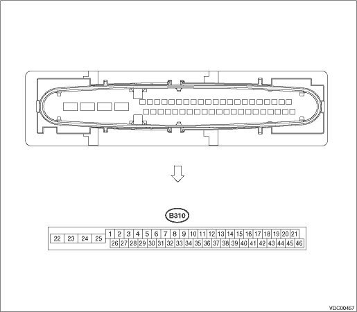
• Terminal numbers in VDCCM&H/U connector are shown in the figure.
• When the connector is removed from the VDCCM&H/U, the ABS warning light, VDC warning light, VDC OFF indicator light, and the hill start assist warning light illuminate.
|
Content |
Terminal No. (+) — (−) |
Input/Output signal | ||
|
Measured value and measuring conditions | ||||
|
Power supply |
28 — 25 |
10 — 15 V when the ignition switch is ON. | ||
|
ABS wheel speed sensor |
Front LH wheel |
Power supply |
26 — 25 |
4.5 — 16.5 V |
|
Signal |
1 |
5.9 — 16.8 mA: Rectangle waveform | ||
|
Front RH wheel |
Power supply |
5 — 25 |
4.5 — 16.5 V | |
|
Signal |
6 |
5.9 — 16.8 mA: Rectangle waveform | ||
|
Rear LH wheel |
Power supply |
2 — 25 |
4.5 — 16.5 V | |
|
Signal |
27 |
5.9 — 16.8 mA: Rectangle waveform | ||
|
Rear RH wheel |
Power supply |
3 — 25 |
4.5 — 16.5 V | |
|
Signal |
4 |
5.9 — 16.8 mA: Rectangle waveform | ||
|
CAN communication line (+) |
35 |
2.5 — 1.5 V pulse signal | ||
|
CAN communication line (−) |
10 |
3.5 — 2.5 V pulse signal | ||
|
Valve relay power supply |
24 — 25 |
10 — 15 V when the ignition switch is ON. | ||
|
Motor relay power supply |
23 — 22 |
10 — 15 V when the ignition switch is ON. | ||
|
Stop light switch |
30 — 25 |
1.5 V or less when the stop light is OFF; otherwise, 10 — 15 V when the stop light is ON. | ||
|
Subaru Select Monitor |
7 — 25 |
0 ←→ 12 V pulse (in communication) | ||
|
Vehicle speed output signal |
33 |
0 ←→ 5 V pulse | ||
|
Ground |
25 |
— | ||