1.CHECK IGNITION SYSTEM FOR SPARKS.
1) Remove the plug cord cap from each spark plug.
2) Install a new spark plug on plug cord cap.
CAUTION:
Do not remove the spark plug from engine.
3) Contact the spark plug thread portion to engine.
4) While opening the throttle valve fully, crank the engine to check that spark occurs at each cylinder.
|
Does spark occur at each cylinder?
|
Check fuel pump system. 
|
|
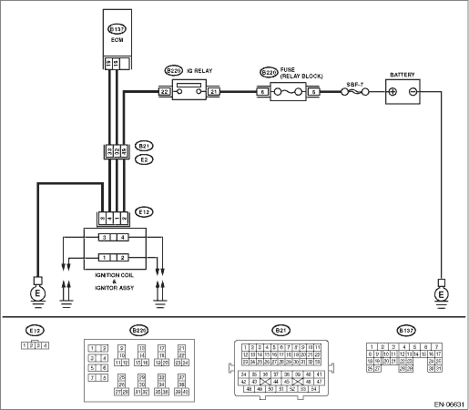
2.CHECK POWER SUPPLY CIRCUIT FOR IGNITION COIL AND IGNITOR ASSEMBLY.
1) Turn the ignition switch to OFF.
2) Disconnect the connector from the ignition coil and ignitor assembly.
3) Turn the ignition switch to ON.
4) Measure the voltage between ignition coil and ignitor assembly connector and engine ground.
Connector & terminal
(E12) No. 2 (+) — Engine ground (−):
|
Is the voltage 10 V or more?
|
|
Repair the harness and connector.
NOTE:
In this case, repair the following item:
• Open circuit of harness between the ignition coil and ignitor assembly connector and main relay connector
• Poor contact of coupling connector
• Blown out of fuse
|
3.CHECK HARNESS OF IGNITION COIL AND IGNITOR ASSEMBLY GROUND CIRCUIT.
1) Turn the ignition switch to OFF.
2) Measure the resistance between the ignition coil and ignitor assembly connector, and engine ground.
Connector & terminal
(E12) No. 3 — Engine ground:
|
Is the resistance less than 5 Ω?
|
|
Repair the open circuit in harness between ignitor assembly connector and engine ground.
|
4.CHECK IGNITION COIL AND IGNITOR ASSEMBLY.
1) Remove the spark plug cords.
2) Measure the resistance between spark plug cord contact portions to check secondary coil.
|
Is the resistance 10 — 15 kΩ?
|
|
Replace the ignition coil and ignitor assembly.
|
5.CHECK INPUT SIGNAL FOR IGNITION COIL AND IGNITOR ASSEMBLY.
1) Connect the connector to the Ignition coil and ignitor assembly.
2) Check if voltage varies synchronously with engine speed when cranking, while monitoring voltage between ignition coil and ignitor assembly connector and engine ground.
Connector & terminal
(E12) No. 1 (+) — Engine ground (−):
(E12) No. 4 (+) — Engine ground (−):
|
Does the voltage vary 10 V or more?
|
|
Replace the ignition coil and ignitor assembly.
|
6.CHECK HARNESS BETWEEN ECM CONNECTOR AND IGNITION COIL AND IGNITOR ASSEMBLY CONNECTOR.
1) Turn the ignition switch to OFF.
2) Disconnect the connectors from the ECM.
3) Disconnect the connector from the ignition coil and ignitor assembly.
4) Measure the resistance of harness between ECM connector and ignition coil and ignitor assembly connector.
Connector & terminal
(B137) No. 18 — (E12) No. 1:
(B137) No. 19 — (E12) No. 4:
|
Is the resistance less than 1 Ω?
|
|
Repair the harness and connector.
NOTE:
In this case, repair the following item:
• Open circuit in harness between ECM connector and ignition coil and ignitor assembly connector
• Poor contact of coupling connector
|
7.CHECK HARNESS BETWEEN ECM CONNECTOR AND IGNITION COIL AND IGNITOR ASSEMBLY CONNECTOR.
Measure the resistance of harness between ECM connector and engine ground.
Connector & terminal:
(B137) No. 18 — Engine ground:
(B137) No. 19 — Engine ground:
|
Is the resistance 1 MΩ or more?
|
Repair the poor contact of the ECM connector.
|
Repair the ground short circuit of harness between ECM connector and ignition coil and ignitor assembly connector.
|