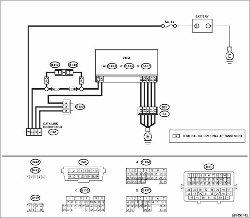
1.CHECK POWER SUPPLY CIRCUIT.
Connect the SDI (Subaru Diagnosis Interface) or general scan tool to data link connector.
|
Does SDI or general scan tool turn ON?
|
|
|
2.CHECK POWER SUPPLY CIRCUIT.
Measure the voltage between data link connector and chassis ground.
Connector & terminal
(B40) No. 16 (+) — Chassis ground (−):
|
Is the voltage 10 V or more?
|
|
Repair the power supply circuit.
NOTE:
In this case, repair the following item:
• Open or ground short circuit of harness between battery and data link connector
• Blown out of fuse (M/B No. 13)
|
3.CHECK HARNESS BETWEEN DATA LINK CONNECTOR AND CHASSIS GROUND.
1) Turn the ignition switch to OFF.
2) Measure the resistance of harness between data link connector and chassis ground.
Connector & terminal
(B40) No. 4 — Chassis ground:
(B40) No. 5 — Chassis ground:
|
Is the resistance less than 5 Ω?
|
Repair the poor contact of data link connector.
|
Repair the harness and connector.
NOTE:
In this case, repair the following item:
• Open circuit of harness between ECM and data link connector
• Open circuit of harness between ECM and engine ground
• Poor contact in ECM connector
• Poor contact of coupling connector
|
4.CHECK HARNESS BETWEEN ECM AND DATA LINK CONNECTOR.
1) Disconnect the connector from ECM, TCM, VDC CM, airbag CM and body integrated unit.
CAUTION:
When disconnecting the connector from airbag control module, always follow the precautions on AB section. 
2) Measure the resistance of harness between ECM and data link connector.
Connector & terminal
(B136) No. 16 — (B40) No. 7:
|
Is the resistance less than 1 Ω?
|
|
Repair the harness and connector.
NOTE:
In this case, repair the following item:
• Open circuit of harness between ECM and data link connector
• Poor contact of coupling connector (LHD model)
|
5.CHECK HARNESS BETWEEN ECM AND DATA LINK CONNECTOR.
Measure the resistance between data link connector and chassis ground.
Connector & terminal
(B40) No. 7 — Chassis ground:
|
Is the resistance 1 MΩ or more?
|
Repair the poor contact in the ECM or data link connector.
|
Repair the ground short circuit of harness between ECM and data link connector.
|