1.CHECK ANTENNA CIRCUIT.
1) Turn the ignition switch to OFF.
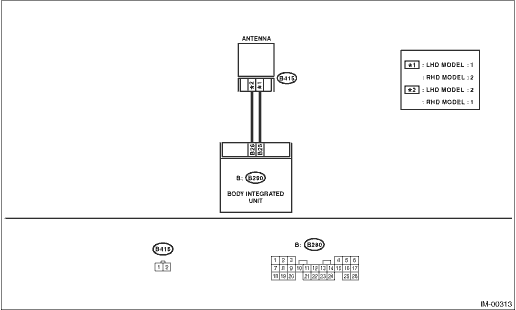
2) Disconnect the harness connector from the antenna. 
3) Measure the resistance of the antenna circuit.
|
Is the resistance less than 10 Ω?
|
|
Replace the antenna.
|
2.CHECK ANTENNA CIRCUIT.
1) Disconnect the harness connector from the body integrated unit.
2) Measure the resistance between harness connector and chassis ground.
Connector & terminal
(B280) No. 26 — Chassis ground:
|
Is the resistance less than 10 Ω?
|
|
|
3.CHECK ANTENNA CIRCUIT.
Measure the resistance between harness connector and chassis ground.
Connector & terminal
(B280) No. 25 — Chassis ground:
|
Is the resistance less than 10 Ω?
|
|
|
4.CHECK ANTENNA CIRCUIT.
1) Turn the ignition switch to ON. (engine OFF)
2) Measure the voltage between harness connector and chassis ground.
Connector & terminal
(B280) No. 25 (+) — Chassis ground (−):
|
|
|
|
5.CHECK ANTENNA CIRCUIT.
Measure the voltage between harness connector and chassis ground.
Connector & terminal
(B280) No. 26 (+) — Chassis ground (−):
|
|
|
Because the battery voltage or ignition switch “ON” circuit is shorted, repair the harness between the body integrated unit and antenna.
|
6.CHECK BODY INTEGRATED UNIT FUNCTION.
1) Turn the ignition switch to OFF.
2) Connect the harness connector to the body integrated unit.
3) Insert the key into the ignition switch, then measure changes in voltage between the antenna harness connectors.
Connector & terminal
(B280) No. 25 (+) — No. 26 (−):
|
Is the voltage −30 — 30 V? (Approx. 0.1 second after inserting the key) Is the voltage 0 V? (Approx. 1 second after inserting the key)
|
|
Replace the body integrated unit, Replace all ignition keys (including the transponder). Execute the registration procedure next. Refer to the “PC application help for Subaru Select Monitor”.
|
7.CHECK IGNITION KEY (TRANSPONDER).
1) Remove the key from ignition switch.
2) Start the engine using other key which is already registered.
|
|
Replace the ignition key (including the transponder). Execute the registration procedure next. Refer to the “PC application help for Subaru Select Monitor”.
|
Replace the body integrated unit, Replace all ignition keys (including the transponder). Execute the registration procedure next. Refer to the “PC application help for Subaru Select Monitor”.
|