LAN SYSTEM (DIAGNOSTICS) > Diagnostic Procedure with Diagnostic Trouble Code (DTC)

DTC U1201 CAN-HS COUNTER ABNORMAL

DTC DETECTING CONDITION:

Communication is unstable because of high speed CAN communication error.

TROUBLE SYMPTOM:

Malfunction indicator light illuminates.
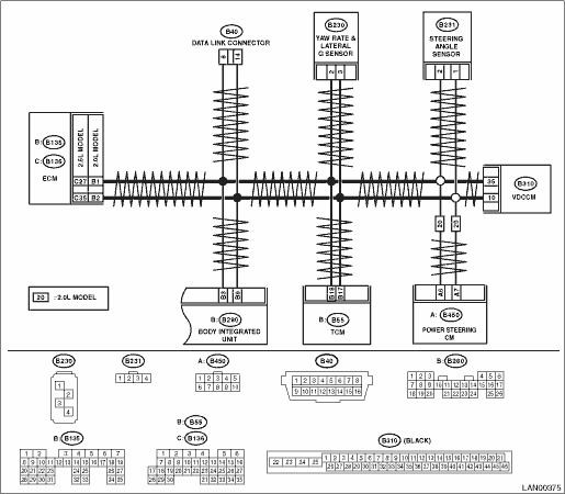
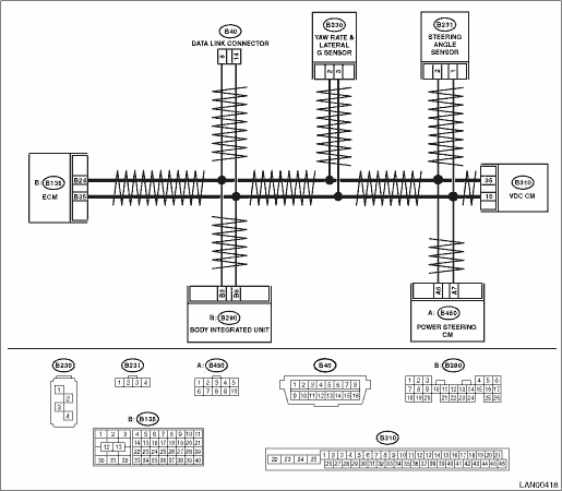
WIRING DIAGRAM:

Gasoline engine model

Diesel engine model

STEPCHECKYESNO

1.CHECK DTC.

Using the Subaru Select Monitor, read all DTCs.

Are there DTCs other than U1201?

Perform the diagnosis according to DTC.

2.CHECK DTC.

Check DTC indicated by body integrated unit.

Is U1201 a current malfunction?

3.CHECK DTC.

1) Turn the ignition switch to OFF.

2) Disconnect all connectors (B280, B310, B55, B135 or B136, B230, B231, B450) that are connected to high speed CAN communication line.

3) Connect all the disconnected connectors.

4) Read the DTC of body integrated unit using Subaru Select Monitor.

Is U1201 a current malfunction?

2.0 L model:

2.5 L model:

4.CHECK ELECTRIC POWER STEERING.

NOTE:

If the vehicle is equipped with hydraulic power steering, go to next.

1) Turn the ignition switch to OFF.

2) Disconnect the electric power steering CM connector (B450).

3) Read the DTC of body integrated unit using Subaru Select Monitor.

Is U1201 a current malfunction?

5.CHECK TCM.

NOTE:

If the vehicle is MT model, go to next.

1) Turn the ignition switch to OFF.

2) Disconnect the TCM connector (B55).

3) Read the DTC of body integrated unit using Subaru Select Monitor.

Is U1201 a current malfunction?

6.CHECK STEERING ANGLE SENSOR.

1) Turn the ignition switch to OFF.

2) Connect the TCM connector.

3) Disconnect the steering angle sensor connector (B231).

4) Read the DTC of body integrated unit using Subaru Select Monitor.

Is U1201 a current malfunction?

7.CHECK YAW RATE SENSOR.

1) Turn the ignition switch to OFF.

2) Connect the steering angle sensor connector.

3) Disconnect the yaw rate sensor connector (B230).

4) Read the DTC of body integrated unit using Subaru Select Monitor.

Is U1201 a current malfunction?

8.CHECK VDC/ABS CM.

1) Turn the ignition switch to OFF.

2) Connect the yaw rate sensor connector.

3) Disconnect the VDC/ABS CM connector (B310).

4) Install the 120 Ω resistance to VDC/ABS CM connector terminals.

Terminals

(B310) No. 10 — No. 35:

5) Using the tester, measure the resistance between terminals of data link connector.

Connector & terminal

(B40) No. 6 — No. 14:

Is the resistance 60 Ω?

9.CHECK DTC.

Read the DTC of body integrated unit using Subaru Select Monitor.

Is U1201 a current malfunction?

10.CHECK DTC.

Read the DTC of body integrated unit using Subaru Select Monitor.

Is U1202 a current malfunction?

Replace the VDC/ABS CM.

11.CHECK ECM.

1) Turn the ignition switch to OFF.

2) Connect the VDC/ABS CM.

3) Disconnect the ECM connector (B135 or B136).

4) Install the 120 Ω resistance to ECM connector.

Terminals

2.0 L model

(B135) No. 1 — No. 2:

2.5 L model

(B136) No. 27 — No. 35:

Diesel engine model

(B135) No. 24 — No. 35:

5) Using the tester, measure the resistance between terminals of data link connector.

Connector & terminal

(B40) No. 6 — No. 14:

Is the resistance 60 Ω?

Repair or replace the open circuit of harness.

12.CHECK DTC.

Read the DTC of body integrated unit using Subaru Select Monitor.

Is U1201 a current malfunction?

Repair or replace the open circuit of measured related harness.

13.CHECK DTC.

Read the DTC of body integrated unit using Subaru Select Monitor.

Is U1202 a current malfunction?

Replace the ECM.

14.CHECK DTC.

1) Reconnect all the disconnected connectors.

2) Read the DTC of body integrated unit using Subaru Select Monitor.

Is U1201 a current malfunction?

Replace the body integrated unit.

15.CHECK HARNESS.

1) Shake the instrument harness and bulkhead harness, rear harness.

2) Read the DTC of body integrated unit using Subaru Select Monitor.

Is U1201 a current malfunction?

Repair or replace the harness.

16.CHECK CONNECTOR.

1) Disconnect the connector used for CAN circuit.

2) Check the connector terminal.

Is there poor contact of connector terminal?

Repair the connector terminal where poor contact exists, or replace harness.

Replace the ECM.

17.CHECK HARNESS.

Using the tester, check the harness between terminals of data link connector and electric power steering CM.

Connector & terminal

Check open circuit

(B40) No. 14 — (B450) No. 7:
(B40) No. 6 — (B450) No. 6:

Check short circuit

(B450) No. 6 — Chassis ground:
(B450) No. 7 — Chassis ground:
(B450) No. 6 — No. 7:

Is harness normal?

Replace the EPS CM.

Repair or replace the harness.

18.CHECK HARNESS.

Using the tester, measure the resistance between terminals of data link connector and TCM.

Connector & terminal

(B40) No. 14 — (B55) No. 17:

(B40) No. 6 — (B55) No. 18:

Is the resistance less than 10 Ω?

Repair or replace the harness.

19.CHECK HARNESS.

Using the tester, measure the resistance between terminals of data link connector and steering angle sensor.

Connector & terminal

(B40) No. 14 — (B231) No. 1:

(B40) No. 6 — (B231) No. 2:

Is the resistance less than 10 Ω?

Repair or replace the harness.

20.CHECK HARNESS.

Using the tester, measure the resistance between terminals of data link connector and yaw rate sensor.

Connector & terminal

(B40) No. 14 — (B230) No. 3:

(B40) No. 6 — (B230) No. 2:

Is the resistance less than 10 Ω?

Replace the yaw rate sensor.

Repair or replace the harness.