|
|
Is the ignition switch ON?
|
|
Turn the ignition switch to ON, and select the power steering mode using the Subaru Select Monitor.
|
2.CHECK BATTERY.
1) Turn the ignition switch to OFF.
2) Measure the battery voltage.
|
Is the voltage 12 V or more?
|
|
Charge or replace the battery.
|
3.CHECK BATTERY TERMINAL.
|
Is there poor contact at battery terminal?
|
Repair or tighten the battery terminal.
|
|
4.CHECK SUBARU SELECT MONITOR COMMUNICATION.
1) Turn the ignition switch to ON.
2) Using the Subaru Select Monitor, check whether communication to other systems can be executed normally.
|
Is the system name displayed on Subaru Select Monitor?
|
|
|
5.CHECK SUBARU SELECT MONITOR COMMUNICATION.
1) Turn the ignition switch to OFF.
2) Disconnect the power steering control module connector.
3) Turn the ignition switch to ON.
4) Check whether communication to other systems can be executed normally.
|
Is the system name displayed on Subaru Select Monitor?
|
Replace the power steering control module. 
|
|
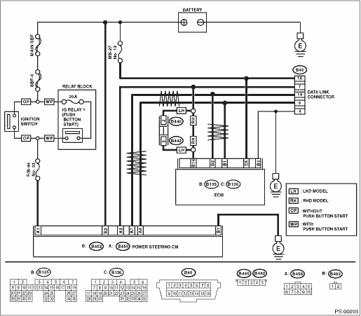
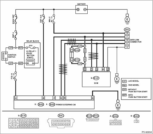
6.CHECK HARNESS CONNECTOR BETWEEN EACH CONTROL MODULE AND DATA LINK CONNECTOR.
1) Turn the ignition switch to OFF.
2) Disconnect the power steering control module and the ECM.
3) Measure the resistance between data link connector and chassis ground.
Connector & terminal
(B40) No. 7 — Chassis ground:
|
Is the resistance 1 MΩ or more?
|
|
Repair the harness and connector between each control module and data link connector.
|
7.CHECK HARNESS CONNECTOR BETWEEN POWER STEERING CONTROL MODULE AND DATA LINK CONNECTOR.
1) Turn the ignition switch to ON.
2) Measure the voltage between the power steering control module and chassis ground.
Connector & terminal
(B40) No. 7 (+) — Chassis ground (−):
|
Is the voltage less than 1 V?
|
|
Repair the harness and connector between each control module and data link connector.
|
8.CHECK HARNESS CONNECTOR BETWEEN POWER STEERING CONTROL MODULE AND DATA LINK CONNECTOR.
Measure the resistance between the power steering control module connector and the data link connector.
Connector & terminal
(B450) No. 2 — (B40) No. 7:
|
Is the resistance less than 0.5 Ω?
|
|
Repair the harness and connectors between the power steering control module and data link connector.
|
9.CHECK POWER STEERING CONTROL MODULE CONNECTOR INSTALLATION.
Turn the ignition switch to OFF.
|
Is the power steering control module connector inserted into the power steering control module until the clamp locks?
|
|
Insert the power steering control module connector into the power steering control module.
|
10.CHECK POWER SUPPLY CIRCUIT.
1) Turn the ignition switch to OFF.
2) Disconnect the power steering control module connector (B452).
3) Turn the ignition switch to ON. (engine OFF)
4) Measure the ignition power supply voltage between the power steering control module connector and chassis ground.
Connector & terminal
(B450) No. 1 (+) — Chassis ground (−):
(B452) No. 2 (+) — Chassis ground (−):
|
Is the voltage 10 — 15 V?
|
|
Repair the open circuit in the harness between the power steering control module and the battery.
|
11.CHECK HARNESS CONNECTOR BETWEEN POWER STEERING CONTROL MODULE AND CHASSIS GROUND.
1) Turn the ignition switch to OFF.
2) Disconnect the connector from the power steering control module.
3) Measure the resistance in the harness between the power steering control module and chassis ground.
Connector & terminal
(B452) No. 1 — Chassis ground:
|
Is the resistance less than 0.5 Ω?
|
|
Repair the open circuit or poor contact of the harness between the power steering control module and chassis ground.
|
12.CHECK POOR CONTACT OF CONNECTOR.
|
Is there poor contact of control module power supply, ground circuit and data link connector?
|
|
Replace the power steering control module.
|