
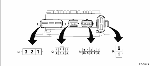
NOTE:
The terminal numbers of the power steering control module connectors are as indicated in the figure.
|
Content |
Terminal No. |
Input/output signal |
|
Measured value and measuring conditions | ||
|
Power supply (IG SW) |
A1 |
Battery voltage is detected with the ignition switch ON when measuring between A1 - B1. |
|
Subaru Select Monitor communication line |
A2 |
Digital signal; can not be measured |
|
Shield GND |
A3 |
0 V is constantly detected |
|
Main torque sensor |
A4 |
The resistance changes when the steering is operated to the right or left with the ignition switch ON. |
|
Sub torque sensor |
A5 |
The resistance changes when the steering is operated to the right or left with the ignition switch ON. |
|
CAN communication |
A6 |
Digital signal; can not be measured |
|
CAN communication |
A7 |
Digital signal; can not be measured |
|
Torque sensor ground |
A9 |
0 V is constantly detected |
|
Torque sensor power supply |
A10 |
Approximately 5 V is detected with ignition switch ON. |
|
Ground |
B1 |
Battery voltage is constantly detected when measuring between B1 - B2. |
|
Power supply |
B2 | |
|
Resolver S1 |
C1 |
Varies depending on the operational status of the motor. |
|
Resolver S3 |
C2 | |
|
Resolver S2 |
C3 | |
|
Resolver S4 |
C4 | |
|
Resolver R1 |
C5 | |
|
Resolver R2 |
C6 | |
|
Motor W phase |
D1 |
Varies depending on the motor output. |
|
Motor V phase |
D2 | |
|
Motor U phase |
D3 |