KEYLESS ACCESS WITH PUSH BUTTON START SYSTEM (DIAGNOSTICS) > Diagnostic Procedure with Diagnostic Trouble Code (DTC)
DTC DETECTING CONDITION:
The vehicle speed sensor output abnormal signals.
CAUTION:
When the power supply CM is replaced with a new unit, and the battery ground terminal is connected, it will become ignition ON. Also, if the battery is disconnected, it will resume to a condition with the battery cut off.
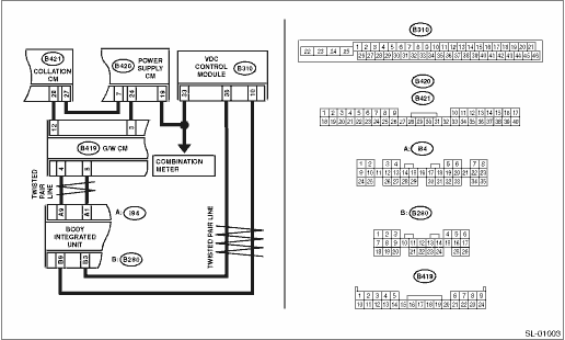
WIRING DIAGRAM:

1.CHECK DTC.
1) Drive for 30 seconds at approximately 30 km/h or more.
2) Read power supply CM DTCs using the Subaru Select Monitor.
|
|
|
Refer to the vehicle speed signal error of B2116.
|
2.CHECK COMBINATION METER.
Perform the self-diagnosis of combination meter. 
|
Is the self-diagnosis of combination meter OK?
|
|
Replace the combination meter.
|
3.CHECK CURRENT DATA.
Using the Subaru Select Monitor, confirm the current data «Front Wheel Speed» of the body integrated unit while driving.
|
Does the data increase or decrease according to the driving condition?
|
Replace the combination meter.
|
|
4.CHECK CURRENT DATA.
Using the Subaru Select Monitor, display the current data «Vehicle Speed Signal» of the ECM while driving.
|
Does the data increase or decrease according to the driving condition?
|
Replace the combination meter.
|
|
5.CHECK CURRENT DATA.
Using the Subaru Select Monitor, confirm the ABS/VDC CM current data for «Vehicle speed signal» for the 4 individual wheels while driving.
|
Do the data for the 4 wheels all increase or decrease by the same figure according to the driving condition?
|
|
Check the ABS/VDC CM vehicle speed signal circuit.
|
6.CHECK WIRING HARNESS.
1) Disconnect the ABS/VDC CM connector.
2) Using a tester, measure the voltage between the ABS/VDC CM connector and chassis ground when the ignition switch is turned OFF and to ON.
Connector & terminal
(B310) No. 33 — Chassis ground:
|
Does the voltage change from less than 1 V → 8 V or more?
|
|
Check the ABS/VDC CM vehicle speed signal circuit.
|
7.CHECK WIRING HARNESS.
1) Disconnect the combination meter connector.
2) Using a tester, check continuity between the ABS/VDC CM connector and the combination meter.
Connector & terminal
(B310) No. 33 — (i10) No. 19:
|
|
|
Repair or replace the open circuit of harness.
|
8.CHECK COMBINATION METER.
1) Connect the ABS/VDC CM connector.
2) Using an oscilloscope, check the combination meter input signal (pulse).
Connector & terminal
(i10) No. 19 (+) — Chassis ground (−):
|
Does the pulse cycle become shorter as the speed increases?
|
Replace the combination meter.
|
Replace the ABS/VDC CM.
|